Upstream protection for short circuit current

We are providing some lighting dimmer panels (they also provide hard power and switched power - configurable on a per-channel basis) for a theatre installation.  All the dimmer outputs are 10A single phase circuits and the dimmer has a 3-phase supply.

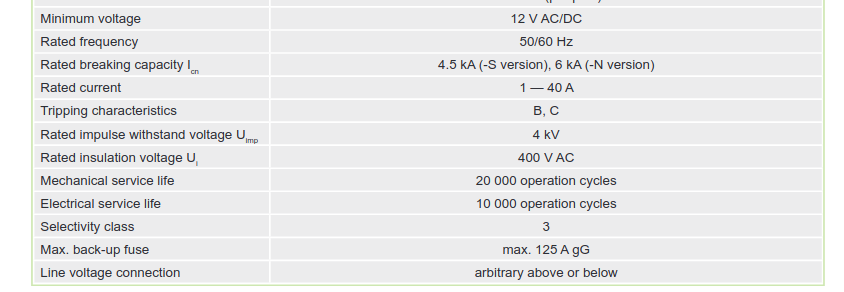
The electrical consultant has stated that the worst case PFC for a fault at the dimmer outputs is approx 9kA - presumably this is on a bolted phase-phase short..  The dimmers are provided with 6kA breaking capacity Type C 10A MCBs (to EN 60898) with neutral disconnect for their output circuits. The consultant is saying that these must be replaced with 10kA devices.  This of course is not a simple matter as the product is CE/UKCA marked and such a modification would likely require a re-certification by the manufacturer with significant cost and time impacts.  Clearly we can't simply swap the devices over ourselves and the manufacturers are not keen to do it either.

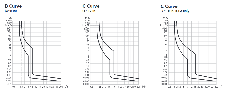
The upstream protective device is a 80A Type D MCB to EN60947-2 (fixed - non adjustable), and has a breaking capacity of 10kA. Looking at the trip time curve for that device once you get to around 800A you hit the 'instantaneous' region.  Likewise for the dimmer MCB once you hit 100A you are in the 'instantaneous' region.

My argument is that if there If there is a fault current of 1kA-6kA, you're likely to be in to a race between the 80A and 10A breakers where you can't predict the winner anyway, and in the worst case of a fault current >6kA and the 10A MCB welds shut the 80A MCB will open within it's fastest possible operation anyway (sub 0.1s).

Also, on a 4mm2 CSA output cable by my calculations once you get to about 8m of cable the worst case fault current is dropped to 6kA anyway.

434.5.1 provides for a higher breaking capacity device upstream to provide protection for a downstream device, although energy let-through needs to be considered.

Is my logic correct or flawed, and is there anything else we would need to do to determine if the configuration decsribed above is compliant?  We know the very high fault current would be an edge-case in terms of likelihood but the electrical consultant is very particular on this project.

NB - We have looked at alternative manufacturers of similar products (there aren't many) and they all use 6kA MCBs.  There is a 'bigger brother' product with higher breaking capacity which won't fit physically and would have a significant cost uplift that I expect will not be feasible.

Thanks in advance.

Jason.

Parents
  • This of course is not a simple matter as the product is CE/UKCA marked and such a modification would likely require a re-certification by the manufacturer with significant cost and time impacts.

    Why do you need a CE marking? My understanding is that a CE marking is required to be applied by the manufacturer when selling a product within the EU/UK. I'm not aware of any requirement for the user to install only CE marked products - although I'm happy to be corrected.

  • If I interpret your post correctly, the manufacturer can provide an ICC along with a condition (or set of conditions) that must be met for that rating to apply - e.g. an upstream OCPD specification.  Might that include for example a maximum energy let-through figure for the upstream device?

    Yes, or say a particular specification (standard, rating and type) of fuse etc.

    (along with the request for the 'internal resistance' value or the dimmer)

    I did have a thought about this ... and decided it's probably not worth pursuing, because if the fault occurs inside the dimmer, only part of, or perhaps little or none of, the internal resistance might be included in the short-circuit path, but we still would want to be happy the dimmer didn't set on fire or cause other hazards.

    I can see where the suggestion came from, but with short-circuit current calculations in BS 7671 ('adiabatic') we consider a fault anywhere on the circuit. More traditionally, when a single fuse is used for a circuit, the "worst case" would be at the far end of the circuit (or a check at each end might do the trick) ... but with circuit breakers, or "combined protection" (two protective devices), things get more tricky, and the worst-case might be at the supply end of the circuit.

  • Yes - the internal resistance concept was originally based around the expressed concern that the MCB's, which are normally at the output, are only rated at 6kA and the PFC may be 9kA.  For that specific issue, the internal resistance would be in play, but your point about the assessment 'through the product' definitely widens the scope of that discussion. 

    At the input to the dimmer, the wiring is protected by a 10kA rated device and I'm assuming the consultant has done his adiabatic correctly for that bit of the circuit, but the 'internal analysis' through the dimmer could be much more complex and would rely on the manufacturer.

    If we don't get to an engineered and accepted solution the alternatives are not great for the project.  There is a 'bigger brother' ETC product with a much larger form factor that likely won't fit in the room and will have significant cost impact for the project.

  • yes, but in self certification route,  the design authority have to decide first which standards and secondly which bits of which standards are actually applicable to their case. Almost no-one uses the notified body route, so no-one external is marking the homework before going to market as it were, and the correct answer is not 'test everything' that is impossible to pass with conflicting requirements.

    Being responsible for getting a product through CE marking can actually become incredibly stressful, as there is a serious risk of missing stuff that others may later decide is relevant or of failing something due to a test that actually should not have been considered relevant. It is  something I have occasionally had to do, and I don't like it.

    There are a lot of occasions when you see  stuff that seems to be sold  with a CE mark  certificate and a rather 'oh sod it' short list of tests that may be deliberate, or just a limitation of the folk doing it.

    Mike

  • "because if the fault occurs inside the dimmer, only part of, or perhaps little or none of, the internal resistance might be included in the short-circuit path, but we still would want to be happy the dimmer didn't set on fire or cause other hazards."

    Yes, bur given its a steel box, one can very quickly set a very high bar, to the total liberated energy permissible, as all that is required is to contain the arc so the flash does not set fire to the curtains, and to catch all the flying bits  - nothing has to survive to work again, as by then it is a repair job anyway.

    It may be informative to consider that more in the manner of a blast calculation.

    Thinks like cheaper laptop power supplies use PCB track as open fuses for example, because the containment means it is fine.

    Mike.

  • Noark are well were,  a North American company, but part of the Chint group,  and generally their European 240V 50Hz  product line is the same as their 277V 60Hz measured against a different set of tests.

    Without knowing the exact breaker part no, this may be about right - 'US web data for noark Din Rail breakers

    Unlike much European data, they give curves that go far enough into overload to really show the time limiting of the mechanism. For the 'C' type, a factor of 20 in current gets you from about 10msec to about 5msec.

    Edit readng back up the thread, and now knowning the part no (oops) here is the datashet

    one sees the 6kA is an ICN (so will break, may not survive) and then further down the line

    "max back-up fuse 125A gG" so there is already a reliance on upstream time / energy limiting to achieve the 6kA level.

    Mike.

  • Yes, bur given its a steel box, one can very quickly set a very high bar, to the total liberated energy permissible, as all that is required is to contain the arc so the flash does not set fire to the curtains, and to catch all the flying bits  - nothing has to survive to work again, as by then it is a repair job anyway.

    It may be informative to consider that more in the manner of a blast calculation.

    That is up to the manufacturer to consider that, it's outside the scope of BS 7671.

    This is the rub for the installer.

  • Unlike much European data, they give curves that go far enough into overload to really show the time limiting of the mechanism. For the 'C' type, a factor of 20 in current gets you from about 10msec to about 5msec.

    The I2t curves will usually be provided separately for discrete ranges of prospective fault current.

    "max back-up fuse 125A gG" so there is already a reliance on upstream limiting at the 6ka level.

    But that's the breaker, not the dimmer ... therefore, if it were that simple, the dimmer manufacturer would quote an Icc value ... unless they have not considered it? The breaker in the dimmer might be able to take it, but can the rest of the dimmer?

    In this particular case, unless the assembly (dimmer) manufacturer is willing to declare an Icc value, along with an appropriate protective device upstream, I'm not sure this goes anywhere sensible, as far as BS 7671 goes?

    The pertinent issue being, the device that's driving the limit of prospective fault current is an assembly outside the scope of BS 7671, so without the manufacturer's agreement, or a consultant (or designer) taking responsibility for it, there doesn't appear to be a simple mechanism for conformity?

  • The pertinent issue being, the device that's driving the limit of prospective fault current is an assembly outside the scope of BS 7671, so without the manufacturer's agreement, or a consultant (or designer) taking responsibility for it, there doesn't appear to be a simple mechanism for conformity?

    Indeed not - but actually this is a very silly situation, as the person who knows most about the particular situation and condition of use actually is the installer, as they are the only one actually there. 

    My personal feel is that there is almost certainly not any really dangerous problem , but there is certainly an admin  one !

    Also it is a bit naughty of Chint / Noark to declare their devices as 6kA and then hide the equivalent  of " but only when backed up by 125Gg or smaller fuse" about 2/3 of the way down the datasheet !!!

    To me that  is an admission that even if the supply pssc had measured as 5.9 kA, an upstream fuse is required somewhere in any case, to operate and give non destructive coverage of the full range of fault currents. I presume without it the breaker de-latches but is then damaged beyond further use. I'd like to hope that flames don't shoot out the front but you never know.

    And that small but key detail about the essential fuse really ought to be copied into in the dimmer makers instructions too.

    Mike

  • And that small but detail about the essential fuse really ought to be copied into in the dimmer makers instructions too.

    Yes, I think that is a pertinent point.

  • Yes - this comes down to who will sign it off from a design perspective, and I agree that to me this is more of a theoretical and admin problem than a real danger, but finding a full documented/calculable trail to compliance is the challenge here.

    Is one interpretation of the max back-up fuse statement on the data sheet that there must be an upstream protective device that has no greater energy let-through than a 125A Gg fuse, as of course in many instances you may not see a fuse until you get as far as the supplier's intake but there could be a series of MCCBs, MCB,s or other devices in a typical installation.

    That Gg fuse let-through looks to be around 1.7 x 10⁵ A2s.  The let-through of the currently specified upstream MCB on a 9kA fault current is 1.2 x 10⁵ A2s so would that be compatible (purely from the perspective of the MCBs - we'd still need something from the manufacturer about the rest of the dimmer though - but it is fundamentally a metal box?

Reply
  • Yes - this comes down to who will sign it off from a design perspective, and I agree that to me this is more of a theoretical and admin problem than a real danger, but finding a full documented/calculable trail to compliance is the challenge here.

    Is one interpretation of the max back-up fuse statement on the data sheet that there must be an upstream protective device that has no greater energy let-through than a 125A Gg fuse, as of course in many instances you may not see a fuse until you get as far as the supplier's intake but there could be a series of MCCBs, MCB,s or other devices in a typical installation.

    That Gg fuse let-through looks to be around 1.7 x 10⁵ A2s.  The let-through of the currently specified upstream MCB on a 9kA fault current is 1.2 x 10⁵ A2s so would that be compatible (purely from the perspective of the MCBs - we'd still need something from the manufacturer about the rest of the dimmer though - but it is fundamentally a metal box?

Children
No Data