Upstream protection for short circuit current

We are providing some lighting dimmer panels (they also provide hard power and switched power - configurable on a per-channel basis) for a theatre installation.  All the dimmer outputs are 10A single phase circuits and the dimmer has a 3-phase supply.

The electrical consultant has stated that the worst case PFC for a fault at the dimmer outputs is approx 9kA - presumably this is on a bolted phase-phase short..  The dimmers are provided with 6kA breaking capacity Type C 10A MCBs (to EN 60898) with neutral disconnect for their output circuits. The consultant is saying that these must be replaced with 10kA devices.  This of course is not a simple matter as the product is CE/UKCA marked and such a modification would likely require a re-certification by the manufacturer with significant cost and time impacts.  Clearly we can't simply swap the devices over ourselves and the manufacturers are not keen to do it either.

The upstream protective device is a 80A Type D MCB to EN60947-2 (fixed - non adjustable), and has a breaking capacity of 10kA. Looking at the trip time curve for that device once you get to around 800A you hit the 'instantaneous' region.  Likewise for the dimmer MCB once you hit 100A you are in the 'instantaneous' region.

My argument is that if there If there is a fault current of 1kA-6kA, you're likely to be in to a race between the 80A and 10A breakers where you can't predict the winner anyway, and in the worst case of a fault current >6kA and the 10A MCB welds shut the 80A MCB will open within it's fastest possible operation anyway (sub 0.1s).

Also, on a 4mm2 CSA output cable by my calculations once you get to about 8m of cable the worst case fault current is dropped to 6kA anyway.

434.5.1 provides for a higher breaking capacity device upstream to provide protection for a downstream device, although energy let-through needs to be considered.

Is my logic correct or flawed, and is there anything else we would need to do to determine if the configuration decsribed above is compliant?  We know the very high fault current would be an edge-case in terms of likelihood but the electrical consultant is very particular on this project.

NB - We have looked at alternative manufacturers of similar products (there aren't many) and they all use 6kA MCBs.  There is a 'bigger brother' product with higher breaking capacity which won't fit physically and would have a significant cost uplift that I expect will not be feasible.

Thanks in advance.

Jason.

  • It would not necessarily render the installation non-conformant, but yes the manufacturer might not want to take responsibility for the equipment thereafter.

    However, it MIGHT render the installation non-conformant with BS 7671, and become a breach of the Electricity at Work Regulations.

    If you change the breaker for another one, will the semiconductors and PCB tracks remain protected against damage ... and possible fire or other damaging event ... in a short-circuit ?

    This type of issue would be a case of exceeding the ratings, or 'strength and capability', of electrical equipment.

    So, if that were to be the case, possible non-conformity with BS 7671 (Regulations 131.3 and 131.4) and possibly a breach of  Regulation 5 and/or Regulation 11 of the Electricity at Work Regulations 1989.

  • We are in discussion with the manufacturer of the dimmer units about this and they have raised the same issue that they would need to review the entire product if the breaking capacity of the outgoing MCBs were to be increased.  Presumably they have designed and tested  it to be able to withstand fault currents of up to 6kA and the associated energy let-through of their selected protective devices.  I have enquired as to the 'internal resistance' of the unit (as referenced by Mike above) as if that alone would reduce the PSCC at the outputs to below 6kA then it could be OK.  By my very rough maths around 12 milliOhm would be sufficient - and if the worst case is a phase-phase short then that would require a path through 2 different channels on the panel, so 6mOhm each could be enough.

  • if the breaking capacity of the outgoing MCBs were to be increased.  Presumably they have designed and tested  it to be able to withstand fault currents of up to 6kA and the associated energy let-through of their selected protective devices.

    Do you have the make and model details of the circuit-breakers currently installed? There might be a 10kA device available with a lower energy let-through?

  • The dimmers are ETC Colorsource Thrupower units: Link

    They use a Noark MCB (I haven't heard of them either) as their protective device on the outputs: Link

    You raise an interesting point.  ETC as the manufacturer would still need to validate a modification but that may be easier if a 10kA device has a lower energy let-through. There is a Schneider Aciti9 10kA device that looks like it would fit.  Energy let-through/withstand data is not easy to come by with all manufacturers but we could try. 

    We could also look at the upstream fuse suggestion as well.

    These are not yet installed, but they are procured and in our warehouse due to long contract periods and wanting to preserve the purchase price (client decision).

  • Hi jb, how does this consultants opinion fit into the contract? 

  • It has Double Pole RCDs and well as the MCBs, which will also probably be rated at 6kA.

  • PSSC at the origin of the installation is 14.4kA measured

    Wouldn’t trust that, but I suppose what else can you do. Is that PP/0.87 or PN x2. In any event, as I understand it, the reactive component is not included and thus the Ipf would likely be much less, albeit with a lower pf. 
    Below, all up to date calibrated instruments with results taken several times. 

  • Not a simple answer to that one.  We are contracted as a specialist sound and lighting contractor to a main contractor.  A Theatre Consultant specified the dimmer panels and named the ETC product as approved - although we had the freedom to choose another if we wished. The electrical consultant is employed by the end client (venue owner) to serve as the electrical designer - I presume it will be their name in the 'design' box on the certificate.  There is an electrical contractor also employed by the main contractor.  We free-issue the dimmer panels to them for installation and testing of the electrical installation (their names in those boxes).

  • I got the energy let-through curves for the upstream devices.  Looks like around 120,000 A2s at a 9kA fault current.  This should be OK on a 4mmoutgoing cable.  Just need verification from the manufacturer that their dimmers are OK with that let-trough value and I think we should be OK.

  • "....
    according to the national annex of BS EN IEC 61439-3. "


    That's "just" the regulatory acknowledgement of the very real energy-limiting physics of the right sort of fuses. That is something fuses get generally better at for high PSSC,  compared to  mechanical breakers (which struggle to break contacts at supersonic speeds without a lot more cunning that found inside the average MCCB).

    My point is, iff you are confident in your understanding and specification of fuses (and looking at some installations out there, that is quite an 'iff' actually), you don't strictly need an annex to cover the design process and can extend the concept to other currents and system ratings.

    For those not familiar
    nice explanation here page ten this PDF

    https://www.eaton.com/content/dam/eaton/markets/for-safety-sake/files/current-limiting-fuses.pdf

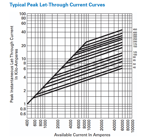
    The rest of the doc is aimed at users of higher voltages bt the principle stands - see extract showing the effect. Note that the fuse needs to be small (no more than a few % of pssc) to start to really limit.

    Mike