Upstream protection for short circuit current

We are providing some lighting dimmer panels (they also provide hard power and switched power - configurable on a per-channel basis) for a theatre installation.  All the dimmer outputs are 10A single phase circuits and the dimmer has a 3-phase supply.

The electrical consultant has stated that the worst case PFC for a fault at the dimmer outputs is approx 9kA - presumably this is on a bolted phase-phase short..  The dimmers are provided with 6kA breaking capacity Type C 10A MCBs (to EN 60898) with neutral disconnect for their output circuits. The consultant is saying that these must be replaced with 10kA devices.  This of course is not a simple matter as the product is CE/UKCA marked and such a modification would likely require a re-certification by the manufacturer with significant cost and time impacts.  Clearly we can't simply swap the devices over ourselves and the manufacturers are not keen to do it either.

The upstream protective device is a 80A Type D MCB to EN60947-2 (fixed - non adjustable), and has a breaking capacity of 10kA. Looking at the trip time curve for that device once you get to around 800A you hit the 'instantaneous' region.  Likewise for the dimmer MCB once you hit 100A you are in the 'instantaneous' region.

My argument is that if there If there is a fault current of 1kA-6kA, you're likely to be in to a race between the 80A and 10A breakers where you can't predict the winner anyway, and in the worst case of a fault current >6kA and the 10A MCB welds shut the 80A MCB will open within it's fastest possible operation anyway (sub 0.1s).

Also, on a 4mm2 CSA output cable by my calculations once you get to about 8m of cable the worst case fault current is dropped to 6kA anyway.

434.5.1 provides for a higher breaking capacity device upstream to provide protection for a downstream device, although energy let-through needs to be considered.

Is my logic correct or flawed, and is there anything else we would need to do to determine if the configuration decsribed above is compliant?  We know the very high fault current would be an edge-case in terms of likelihood but the electrical consultant is very particular on this project.

NB - We have looked at alternative manufacturers of similar products (there aren't many) and they all use 6kA MCBs.  There is a 'bigger brother' product with higher breaking capacity which won't fit physically and would have a significant cost uplift that I expect will not be feasible.

Thanks in advance.

Jason.
  • We have looked at the upstream devices

    When we refer to 'let-through' this more normally refers to energy rather than current.  You can look at trip time curves to see how long a device will take to trip with a certain current, but once you get into the 'instantaneous' trip region of that curve the time value doesn't get any faster, and you would then usually refer to the energy let-through data.  Short-circuit currents are often in this region.

    This is where we got to with this scenario, but ultimately the dimmer manufacturer was not forthcoming with the energy withstand of the dimmer so I am pleased that another engineering solution was found to the problem - as mentioned in my earlier reply.

  • Well it appears they found a longer route for the cables feeding the dimmer panels - sufficiently long that the PSSC drops to acceptable levels.  It didn't need much and the problem seems to be solved.  Thankkfully.

  • What is the make/model of the Supply MCB? If you have the readings from the supply DB you could calculate the expected PFC with the manufacturers current let through Current information

  • if the PSSC has gone down, it sounds like it has been re-measured further into the building or perhaps just with a different instrument Thumbsup
    Repeatable readings at this level are not really possible with normal meter probe type connections - see Lyle's images above. Calculations however require very accurate knowledge of the distribution network cable arrangement.
    If not there may be a substation fuse holder out there corroding and getting ready to fail ;-)

    Mike

  • Yep - same issue.  Did you have confirmation from Varilite about the energy withstand of the Rigswitch that allowed you to be compliant 536.4.2.1 - as mentioned by Graham above?  I have struggled to get that information out of ETC in this case - in fact they have said they can't provide it in any reasonable timescale.

  • I've been following this thread. Had the exact same issue when we installed rigswitches with 6kA RCBOs. The PFC reading was 9KA at the Rigswitch. Got hold of the Supply MCB let through current curves which saved the day

  • Just to circle back on this one, after much more chasing with manufacturers and looking at alternatives, it seems like some form of change in the external network has made this problem go away and the PSSC drops to under 6kA where the dimmers are.  Sounds a little strange to me, and I'm waiting on confirmation but if it makes the problem go away then I will take that as a win.

    Thanks to all for the valuable contributions on this thread - it was a great help.

  • It is an unusual line for an MCB data sheet  certainly, and while I've seen it in other Chint group derived kit, in particular their half width (9mm) MCBs its not seen in fancier brands like Hagar Schneider etc.

    The "CN" subscript is the fault current at which under the stated test conditions, (so only with that fuse I presume) the breaker will break, but it may never work properly again. Beyond that it is not guaranteed to break safely  or indeed to break at all so it may all just blow up.. Usually they don't however ;-)

    Given those breakers, I'd be reserving a space on the wall for some local 80A 'death or glory' fuses in the line myself.

    Mike

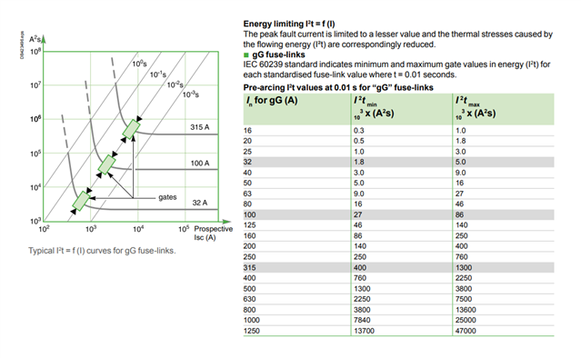
  • I think it's 140,000 A2s but your observation on the flattening out of the energy let-through is correct.

    The Icc statement made could be correct, but we would really need that set out by the manufacturer to be able to rely on it.

  • If I'm reading this correctly then the I2t value for gG fuses flattens out at high prospective fault currents with a maximum of 140 A2s for a 125A fuse.

    So I might interpret the manual of the Noark MCBs to mean:

    Icn = 6kA

    Icc = Infinity kA (in practice limited by the rated breaking capacity of the fuse)