PME / TT Street Cabinet Enclosure Earthing Electrode Values

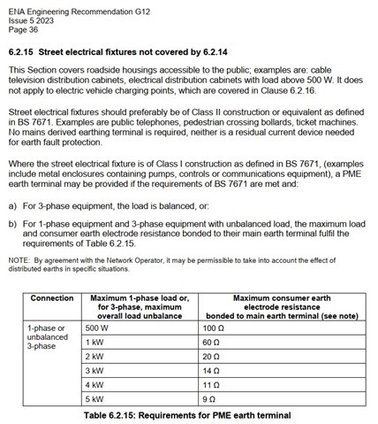
Can anyone shed any light on the arithmetical relationship derivation between the value of earth electrode resistance and power consumption as given in DNO ENA guidance note G12.  

And do these values apply to TT earthed mains powered street furniture. EG telecoms cabinets? 
Parents
  • No, won't apply to TT - these will be all about holding the PEN conductor down to a reasonable voltage when it's suffered an open circuit back to the main Earth at the source. In TT systems the N floating about at a hazardous voltage isn't a worry since it's not connected to exposed parts and the earth electrode only has to be rated to keep the system below 50V where the fault (or leakage) current is just insufficient to trip the RCD - i.e. it's related to the rating of the earth fault protective devices rather than the load.

    The figures above do look a bit odd to me though. Traditionally we used (AFAIK) 20Ω for lamppost (up to 500W) - which kept things below 50V whatever happened. These figures seem substantially higher (by a factor of 4 or 5) though - so there must be some other assumptions going on there, but off the top of my head I'm not sure what.

       - Andy.

  • Looking at those figures again, if you assume the load has a simple resistive nature (i.e. unlike most modern electronic PSUs it doesn't increase its current draw to compensate for a reduced voltage, but the load's resistance in effect remains constant), it looks like those figures will be about the same as the load's resistance - so the load and electrode acting as a potential divider will have about half the supply voltage dropped across each - limiting the tough voltages to 115V-ish. While that's higher than the 50V a.c. we'd normally consider a safe limit, higher figures are sometimes justified  (e.g. 70V for EVSEs)  - so maybe it's a case of fairly good if not perfect balanced with practicality (getting a reliable 20Ω in many soils will be quite a challenge, especially if you don't have an extended area to play with).

       - Andy.

Reply
  • Looking at those figures again, if you assume the load has a simple resistive nature (i.e. unlike most modern electronic PSUs it doesn't increase its current draw to compensate for a reduced voltage, but the load's resistance in effect remains constant), it looks like those figures will be about the same as the load's resistance - so the load and electrode acting as a potential divider will have about half the supply voltage dropped across each - limiting the tough voltages to 115V-ish. While that's higher than the 50V a.c. we'd normally consider a safe limit, higher figures are sometimes justified  (e.g. 70V for EVSEs)  - so maybe it's a case of fairly good if not perfect balanced with practicality (getting a reliable 20Ω in many soils will be quite a challenge, especially if you don't have an extended area to play with).

       - Andy.

Children
No Data