Connection of back-upgenerator to TN-C-S domestic installation

Hi All. I'm a medically retired electrician with additional strings to the bow throughout my career. From contracting on commercial electrical installations to building/designing large industrial containerised generators to managing landfill gas generator installations and finishing at building maintenance engineer covering alot of variable skills with HVAC and BMS.

I try to keep the mind busy and do what I can. 

Appreciate your viewing my question I'll try to be as descriptive as possible. 

My home is TN-C-S supply with no extraneous parts ( water supply is plastic pipe and no gas supply).

Approximately 5 years ago I installed a large metal garage/workshop 7.5m by 4.5m(concrete floor with metal box section frame bolted to the concrete pad) 

I supplied the garage with a 6mm armoured  via 30ma RCD and 40amp MCB ,armour being connected to house distribution board and isolated at the garage termination so as not to export the earth as per regulation,I installed 2m deep electrode and additional 1m deep electrode both wired back to garage DB. So in effect garage is on a TT system.

The house distribution boards (8 way mem bs88 and 4 way mem2000 RCD mcb) I want to change out for 1 large regulation DB , one in looking at is MK dual 100amp 30ma isolator with type 2 SPD rest populated with mcb's.

To the nub of my question. I want to install back up generator (7.5kva peak 6.25kva constant)which will be sited out the back of the metal garage( outside garage building not inside)some approx 12m from house. I'll give you my thoughts on what I'm thinking of installation to ensure complete separation from incoming mains supply to remove chance of any back feed especially under fault condition.

1. Install a single phase 32amp incomer socket ( will be supplied from generator in event of outage)to the exterior of house.

2.Wired back to a 20amp double pole rcbo enclosure in distribution cupboard.

3.From rcbo into a manual 3 pole  transfer switch.

4.The network supply wired the manual 3 pole transfer switch then from transfer switch to new distribution board (dB).

5. The generator chassis will be connected to garage earth electrodes when in use.

6.. 3 pole manual transfer switch? My thinking is to switch L. N. and the earth. 

My thinking on this: when mains is in use garage supply has isolated earth DB side connected only  as previously discussed to protect cable/circuit going to garage rest of house still using supplier earth path . 

When generator supply is used the whole installation house including garage would be effectively TT system this way no chance of back feed to the supplier network including under fault conditions from my/consumer end giving earthing is also switched at the manual transfer switch, i

Q.1.is this 3 pole manual transfer idea (switching earths) idiotic/unnecessary/ not advisable ?

Q. 2. Should I include a type 1 SPD to the 20amp 30ma generator supply enclosure inside distribution cupboard given large metal shed and lighting strikes ? 

Sorry for long winded pre log just trying to ensure you've all the information needed. Would be grateful for your thoughts and indeed advice.
Parents
  • 1. Install a single phase 32amp incomer socket ( will be supplied from generator in event of outage)to the exterior of house.

    You're probably thinking correctly, but just to be absolutely clear (in formal terms and for others reading this) the thing on the outside of the house should be a plug (inlet), rather than a socket - the trailing part (from the generator) should have shrouded socket tubes, rather than exposed pins.

    When generator supply is used the whole installation house including garage would be effectively TT system

    The generator's system would almost certainly be TN-S - the local electrode acting as the "source" earthing (the first T) and c.p.c.s connected to N via the generator's N-PE link (so TN). To create a local TT system, you'd need two separate electrodes, for for the generator and another for the installation.

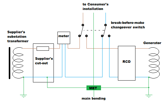
    The usual approach is you use a DP change-over switch (for single phase) and have Earth solidly connected to both a local electrode and the DNO's earth. In Grid mode it's then TN-C-S as before, and TN-S in generator mode.

    You local TT sub-installation for the workshop makes things more interesting. You could leave that as TT, even in generator mode, but you'd need at least two electrodes then, one for the generator and another separate one for the garage/workshop. You just need to make sure that the sum of the two electrode resistances is still gives a low enough loop impedance for ADS etc for your TT system (as your generator electrode is likely to have a higher resistance to Earth than the DNO's).

    One problem with that approach though is the proximity of the generator to the workshop - if it's within reach (2.5m?) they need to be on the same earthing system - which they won't be if the workshop is TT and the house TN. One option then is to bring the workshop onto the house TN system during island mode - perhaps a 3rd pole in your change-over switch could achieve that - but you'd have to be very careful how things were arranged both in grid-connected and island mode - as you'd want to ensure the workshop wasn't connected to the DNO earth, or within reach of the DNO earth, at any time, including when in island mode. Rating a change-over switch contacts to switch between a DNO Earthing facility and extraneous-conductive-parts (e.g. the workshop, presuming it's sat on the ground) can get "interesting" as the currents involved may include distribution network diverted neutral currents, which aren't related to the generator's output rating (consider why you might need 10mm2 main bonding even for tiny installations).

    Maybe one option to consider is to make both the house and workshop one common earthing system - TT in grid mode and TN-S in island mode.

    Diagrams often help. For starters, here's one I prepared for earlier threads, for a simple change-over arrangement:

       - Andy.

  • Hi Andy , Thanks for getting in touch. sorry for delay in responding I had answered back yesterday but hadn't hit the reply.

    You're probably thinking correctly, but just to be absolutely clear (in formal terms and for others reading this) the thing on the outside of the house should be a plug (inlet), rather than a socket - the trailing part (from the generator) should have shrouded socket tubes, rather than exposed pins

    That's correct male plug (exposed pins) mounted on the house as this only becomes energised via cable from generator which would be a female socket with generator end of lead being male .

    The generator's system would almost certainly be TN-S - the local electrode acting as the "source" earthing (the first T) and c.p.c.s connected to N via the generator's N-PE link (so TN). To create a local TT system, you'd need two separate electrodes, for for the generator and another for the installation.

    Yes i recognise its TN-S owing to the neutral earth link in generator.

    Was refencing "effectively  TT" more to the fact installation during DNO supply drop and on gen supply earthing would be to the electrode's and not DNO earth point , bad selection of wording apologies.

    You local TT sub-installation for the workshop makes things more interesting. You could leave that as TT, even in generator mode, but you'd need at least two electrodes then, one for the generator and another separate one for the garage/workshop. You just need to make sure that the sum of the two electrode resistances is still gives a low enough loop impedance for ADS etc for your TT system (as your generator electrode is likely to have a higher resistance to Earth than the DNO's).
    One problem with that approach though is the proximity of the generator to the workshop - if it's within reach (2.5m?) they need to be on the same earthing system - which they won't be if the workshop is TT and the house TN. One option then is to bring the workshop onto the house TN system during island mode - perhaps a 3rd pole in your change-over switch could achieve that - but you'd have to be very careful how things were arranged both in grid-connected and island mode - as you'd want to ensure the workshop wasn't connected to the DNO earth, or within reach of the DNO earth, at any time, including when in island mode. Rating a change-over switch contacts to switch between a DNO Earthing facility and extraneous-conductive-parts (e.g. the workshop, presuming it's sat on the ground) can get "interesting" as the currents involved may include distribution network diverted neutral currents, which aren't related to the generator's output rating (consider why you might need 10mm2 main bonding even for tiny installations).

    My though was to run another 10mm earth cable from nearest earth pit (I've 2 pits linked for garage TT 2m electrode in one and 1m in the other both cabling run separately into garage and joined in esco form esco I've main bonding to garage frame and from esco to garage db) nearest earth pit Appox 4 m from what will be generator location) to the generator this would tie all earthing, earthing rods steel garage and generator keeping them all at equal potential as genset location and steel garage are approx 1.5m apart.

    There is approx 4m separation from garage to house building and some 6m to nearest house electric. if i was to install another earth rod just for generator 1. it wouldn't be as good a read than rods I've installed for garage 2. proximity of new genset electrode to existing electrodes wouldn't be of any benefit would just be an other extraneous conductive part effectively .

    Change over switch ive been looking at is 100 amp or 125 amp, think 100amp is more than suitable given 80amp DNO fused supply, I understand and take the point of ensuring garage earthing and DNO supply earthing is indeed separate I'm going to test this separation today, ill also do clamp test on DNO earth to rule out any other issues, thankyou that's a good point you highlighted.

    With ref to "diverted neutral currents" from DNO this was my reasoning in switching the DNO earth given intention of back up generator is provide power during DNO power outage 99% of time i due to a fault on the DNO network/grid rather than planned maintenance. If I use a  double pole line and neutral isolated bypass (break before make) but with this there is potential for DNO diverted neutral current through the DNO earth and at same time If I tie to DNO earth with generator running and i have a fault my end fault current could potentially be introduced to DNO network.

    The usual approach is you use a DP change-over switch (for single phase) and have Earth solidly connected to both a local electrode and the DNO's earth. In Grid mode it's then TN-C-S as before, and TN-S in generator mode.

    This is my concern if I'm using generator the DNO supply will be off line likely due to a fault and if I've all earths tied to DNO earth and ive a fault at my end will this not sent fault current through the DNO Earth/neutral onto to network?, my other thought on this is the stipulation in G99/NI (as id replied to gkenyon if you could review my reasoning on application of G99/NI and indeed ESQCR ) .  

    Find out more about the Distribution Code for Northern Ireland | Northern Ireland Electricity Networks

    section 7.4.1.4 The Power Generating Facility shall use an earth electrode independent from the Distribution Network.

    Maybe one option to consider is to make both the house and workshop one common earthing system - TT in grid mode and TN-S in island mode.

    Would this not mean in grid mode having the DNO supply N-E link disconnected? ,    this would remove my thought and need for 3 pole bypass but at same time would need to have new earthing cable runs from garage esco/earthing electrodes back to the house. Appreciate that  the TN-S in "island mode" is in ref to the neutral earth link in generator winding/centre tapping.

    For completeness in generator terms, im use to referring to island mode = floating neutral at generator (no neutral earth link or tie) in this format is advised small output generators are only used for one item of class 2 equipment. If more than 1 item of any equipment or indeed hook up to property or building then neutral-earth are to be "tied" in alt winding and earth electrodes used. would you believe I've heard of and seen people linking neutral earth in the plug lead or actually linking in winding on some duel voltage (110v and 230v) generators where the 110v is generated from 55v centre tapping .

    Appreciate any and all feedback and advice, I'm no expert by any means but like to fully understand and indeed question myself so im grateful for any discussion and direction to this end. 

  • if you look at the double pole diagram that Andy posted above, the NE link of the DNO is out of loop when on genset, so that's OK. 
    Dont worry about the DNO earth being surcharged by any fault at your end that will be cleared within 0.2 secs - so you need some sort of RCD on the generator, perhaps 100mA time delay if you really care about discrimination with house RCDs, though I might not be so worried, a 30mA RCD on genset only trips with the double whammy of DNO fault and another one on your side knocking out one or both  RCDs - that is not likely and may be an acceptable risk - perhaps one preferable to a risk not tripping if there really is a fault at home.
    Mike

  • im use to referring to island mode = floating neutral at generator

    Ah, OK. I was using island mode in the sense of your installation being separated from the grid (power wise).

    This is my concern if I'm using generator the DNO supply will be off line likely due to a fault and if I've all earths tied to DNO earth and ive a fault at my end will this not sent fault current through the DNO Earth/neutral onto to network?

    An earth fault in your installation will (presuming the generator don't just stall or its output voltage collapse) may well create voltage differences around your own earth loop - but your earth loop will be referenced to Earth at some point - if your connection to the DNO PE is at the same point, you probably won't be exporting any voltage differences to them.

       - Andy.

  • Hi Mike thankyou. could you possibly explain out of loop, all earths appear to connect at MET in andys drawing

  • you think any earth fault would stay / dissipate with in my earthing system?, the earth rod link to the house MET would be via supply cable in event of power outage with gen in operation and linked to MET then just dp bypass, then run 10mm cable from genset frame to earth pit ive the garage earthing connected from.

    Thanks again appreciate the discussion/advice

Reply
  • you think any earth fault would stay / dissipate with in my earthing system?, the earth rod link to the house MET would be via supply cable in event of power outage with gen in operation and linked to MET then just dp bypass, then run 10mm cable from genset frame to earth pit ive the garage earthing connected from.

    Thanks again appreciate the discussion/advice

Children
No Data