Connection of back-upgenerator to TN-C-S domestic installation

Hi All. I'm a medically retired electrician with additional strings to the bow throughout my career. From contracting on commercial electrical installations to building/designing large industrial containerised generators to managing landfill gas generator installations and finishing at building maintenance engineer covering alot of variable skills with HVAC and BMS.

I try to keep the mind busy and do what I can. 

Appreciate your viewing my question I'll try to be as descriptive as possible. 

My home is TN-C-S supply with no extraneous parts ( water supply is plastic pipe and no gas supply).

Approximately 5 years ago I installed a large metal garage/workshop 7.5m by 4.5m(concrete floor with metal box section frame bolted to the concrete pad) 

I supplied the garage with a 6mm armoured  via 30ma RCD and 40amp MCB ,armour being connected to house distribution board and isolated at the garage termination so as not to export the earth as per regulation,I installed 2m deep electrode and additional 1m deep electrode both wired back to garage DB. So in effect garage is on a TT system.

The house distribution boards (8 way mem bs88 and 4 way mem2000 RCD mcb) I want to change out for 1 large regulation DB , one in looking at is MK dual 100amp 30ma isolator with type 2 SPD rest populated with mcb's.

To the nub of my question. I want to install back up generator (7.5kva peak 6.25kva constant)which will be sited out the back of the metal garage( outside garage building not inside)some approx 12m from house. I'll give you my thoughts on what I'm thinking of installation to ensure complete separation from incoming mains supply to remove chance of any back feed especially under fault condition.

1. Install a single phase 32amp incomer socket ( will be supplied from generator in event of outage)to the exterior of house.

2.Wired back to a 20amp double pole rcbo enclosure in distribution cupboard.

3.From rcbo into a manual 3 pole  transfer switch.

4.The network supply wired the manual 3 pole transfer switch then from transfer switch to new distribution board (dB).

5. The generator chassis will be connected to garage earth electrodes when in use.

6.. 3 pole manual transfer switch? My thinking is to switch L. N. and the earth. 

My thinking on this: when mains is in use garage supply has isolated earth DB side connected only  as previously discussed to protect cable/circuit going to garage rest of house still using supplier earth path . 

When generator supply is used the whole installation house including garage would be effectively TT system this way no chance of back feed to the supplier network including under fault conditions from my/consumer end giving earthing is also switched at the manual transfer switch, i

Q.1.is this 3 pole manual transfer idea (switching earths) idiotic/unnecessary/ not advisable ?

Q. 2. Should I include a type 1 SPD to the 20amp 30ma generator supply enclosure inside distribution cupboard given large metal shed and lighting strikes ? 

Sorry for long winded pre log just trying to ensure you've all the information needed. Would be grateful for your thoughts and indeed advice.
  • Rewinding to the beginning, would it be easier to run a sufficiently large earth wire to the workshop and make it PME, along with the house?

    It might ... BUT some DNOs (and depending how large the metal building is, industry guidance) might not "like" connecting the workshop to PME,

    Whilst the "not PME" guidance for large metal buildings is certainly founded in fact, the carte-blanche application of "TT the outbuilding" is definitely not good, and very limiting given Regulation 411.3.1.1.

    This, and the overall "simultaneous contact" issue, has caused no end of trouble since EV charging came on the scene, even though the approach (formerly the EEB of EEBADS as we used to call it) has been here for some considerable time. As ever, the unforeseen nuances will ever trip us up.

  • Hi Phillip, Thankyou for your contribution.

    The (both earth pit electrodes which are 4m apart fyi) are not at any instanced used separately/independently nor do they rely on impedance reading between them for conductivity. Both earth rod pit electrodes are permanently connected together by means of 2off 10mm earthing cables from each pit (4off 10mm cables)  which are terminated in an esco under the db board inside the garage and form the TT system earthing only. From this esco earth cable goes to garage db and again from esco to framework of the garage.

    The proposed earthing connection to the generator alt/engine/chassis (which will be sited within touching distance of the metal garage) was a 10mm earthing cable to nearest earth pit electrode (some 3-4 metres from the genset)  for clarity no earthing cabling is to be disconnected from the existing, just the addition of another cable from the earth pit electrode to the genset, for a result of equipotential bonding of extraneous conductive parts and to provide path for earth fault current .

    There is no ability for direct contact between the metal garage and house (including any exposed conductive parts of house) due to distance between them..

    The DNO incomer to the house is 8m from 1st earth pit electrode for the garage.

    When i get a chance ill get readings between the two (DNO TN-C-S and TT earth )will also clamp for any earth fault current at DNO.

    From memory earth electrodes to garage db are .2 ohms and several points around the frame of garage do not exceed .6ohms after allowance for fly lead .

  • Rewinding to the beginning, would it be easier to run a sufficiently large earth wire to the workshop and make it PME, along with the house?

    A lot of DNOs don't like PME being used for metal outbuildings (but the rules do seem to vary by region) - same reasoning as EVs or caravans - there's a (small) risk of shock for someone outside stood on the ground and touching the building (or door handle, if the door is also steel).

       - Andy.

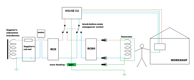
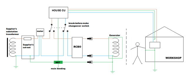
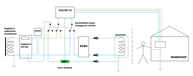
  • If we're to avoid connecting the workshop to PME, I think we've got (at least) 3 options...

    1. Keep the house connected to PME, the workshop TT, and somehow put the generator out of reach of the workshop.

    2. As above, but with some kind of switching to disconnect the DNO's earth when running off the generator (can only work if there are no extraneous-conductive-parts than can import a PME potential from neighbouring properties, and suitable separation from any buried metalwork (and cables) connected to PME).

    3. Just TT the lot (Everything TN-S in off-grid mode, house and workshop on same earthing system all the time) (similar provisos for separation from PME).


    (I've added an up-front RCD on the grid supply for the last one, but it could go after the change-over, or even be omitted if there was double/reinforced insulated all the way to the 1st RCD).

    I suppose you could have a variant of 2 where the PE change-over switch connects the workshop PE to the house MET....

      - Andy.

  • earth pit electrode (one of the two pits of electrodes

    For those times when those two electrodes are not locally/directly connected, what is the impedance between them?

    If I understood correctly you are, at times, using them independently to separate between two earthing 'systems' [hence their 'boundaries' become important], and others, such as the DNO may have assumed different boundaries in their design process Grimacing.

  • So DNO TN-C-S supply now offline, completely isolated, and with it the regulations covering the same TN-C-S supply within customers installation, different supply different regulations now apply

    Not always, you may be connected through extraneous-conductive-parts (gas, water, structural parts of the building, either via direct connection, or due to their proximity to the PME supply cable underground).

    different supply different regulations now apply

    No, ESQCR applies still, you would be operating 'switched alternative' supply to the DNO supply according to Regulation 21 of ESQCR (or Regulation 22 of the ESQCR NI), for which G99 applies, as well as BS 7671. 

    The reason the DNOs support this approach, is there may well be other installations "live" in your area, even if yours is islanded and you have no grid power.

    If I thought there was a way you could argue round this, or some magic of taking away the fact that if your main building has extraneous-conductive-parts, you'd still be connected to PME, I would say so. 

    As I said above, these permutations have been debated.

  • When a fault/break occurs on DNO supply and the PEN conductor is broken = no earthing to house installation from DNO PEN. Agree?

    So DNO TN-C-S supply now offline, completely isolated, and with it the regulations covering the same TN-C-S supply within customers installation, different supply different regulations now apply

    A DNO's broken PEN event is quite "interesting"... note that there's no guarantee that the corresponding line conductors will be broken at the same time (and very often they're not) - which means consumers' loads downstream of the break (in your or neighbouring installations) effectively connect the PEN to line(s). The resulting voltage on the PEN can vary (especially on 3-phase systems where loads on different phases can pull against each other), but in the worst case it can reach full line voltage (230V+10% say). So your installation sees the same 230V on L, N and PE - or in other words 0V difference between L and N - so you think you have a simple power cut ... but your MET is at anything up to 230V nominal above true Earth. As long as you're indoors with all bonding in place you should be fine (as you're inside the equipotential zone). Outdoors it's a bit different - standing on damp soil and touching an exposed- or extraneous-conductive-part can be decidedly risky. Insulating shoes help, as does paintwork, but still the risk is there.

    Having an elevated voltage on PE also means you can have some considerable currents flowing back to Earth via bonding (or even c.p.c.s to Class I items in contact with extraneous-conductive-parts that have some path back to true Earth) - hence the chunky sizes need for PME bonding rather than the 2.5mm2 or 6mm2 previous generations would have used.

    Notice that the risk doesn't go away during a power cut or if you disconnect L & N - as long as there's a connection to the PME system there's a risk - and so "PME conditions" continue to apply.

       - Andy.


  • Hi gkenyon, Thanks again for your input i do appreciate it.

    The issue you can't get around with the arrangement you describe, if using the metal outbuilding's earth electrode, is that when the generator is in use, you will be connecting it to PME (even if it's only through extraneous-conductive-parts in the main building) without suitably-sized main bonding conductors.

    Conflicting requirements I'm afraid.

    If im understanding correctly, Yes the earth electrode would be bonded via 10mm cable to genset, then earth within the genset supply cable to house.  I was proposing 6mm 3 core for the temp supply cable, if used a 4 core 6mm (using 2 cores for earth)? or 3 core 10mm? as per <35mm main conductor size ? sorry if I'm not fully following ,understanding as two separate supplies DNO and Genset.

    In normal operation using DNO supply.

    The DNO PEN conductor gets split to MET in consumers meter cupboard there in all earthing within the customers house installation is referenced back to said MET and in turn PEN conductor. Agree?         

    From the main house db a supply circuit to the external metal garage is run underground via 6mm armoured, earth from armoured is only terminated/grounded at the house db and armour/earth is isolated at garage, the garage earthing is via earthing electrodes. Garage is on TT arrangement supplied from house db circuit via DNO TN-C-S, the earth of which protection to garage supply cable only in case of damage to supply cable  Agree?

    When a fault/break occurs on DNO supply and the PEN conductor is broken = no earthing to house installation from DNO PEN. Agree?

    So DNO TN-C-S supply now offline, completely isolated, and with it the regulations covering the same TN-C-S supply within customers installation, different supply different regulations now apply

    Now setting up for new supply into house from the genset 

    The genset windings 0volt /centre tap reference have a neutral earth link fitted, (this doesn't make any genset outgoing supply circuits "neutral" a PEN conductor) then engine/frame/chassis cabled with 10mm to earth electrode 4 metres away, so if the neutral was broken within the genset itself you still have a direct connection to earth its not lost The genset in and of itself is producing a TN-S supply to all outgoing circuits the earth of which is bonded to extraneous conductive part along the way.       

    This is no different to a DNO TN-S supply, where they would generate power up the line from a generator (with a neutral earth link fitted then grounded to earth) then supplies from which to consumers would be in form of TN-S.

    That's all I've got for now will try address rest later. Thanks again.

  • During mains failure the "genset temp supply cable" plugged in links the outside electrodes to MET in the house, keeping everything inside and outside the installation at equipotential.

    But not equipotential between the workshop and the ground around it - i.e. the reason PME was avoided for the workshop in the first place.

    Edges of equipotential zones are tricky at the best of times. The zones work best when they're entirely contained within something substantially insulating (e.g. dry walls, floors etc of conventional buildings). Using PME outdoors is full of contradictions - it'll actually illegal for boats and caravans, against BS 7671 for electric cars (without mitigating measures e.g. open-PEN detection), frowned upon (and against some DNO rules) for steel buildings, but used without a second thought for street lighting, domestic outside lights and heat pumps outdoors. Often it's a fine balance of risk against mitigating features - generally people grab hold of car doors much more often than lampposts for instance.

    I suppose the next question is whether connecting the frame of a small generator, stood on open ground, to PME - with the intention that someone will have to manually start it during a power outage - is a good idea?

       - Andy.

  • Rewinding to the beginning, would it be easier to run a sufficiently large earth wire to the workshop and make it PME, along with the house?