Connection of back-upgenerator to TN-C-S domestic installation

Hi All. I'm a medically retired electrician with additional strings to the bow throughout my career. From contracting on commercial electrical installations to building/designing large industrial containerised generators to managing landfill gas generator installations and finishing at building maintenance engineer covering alot of variable skills with HVAC and BMS.

I try to keep the mind busy and do what I can. 

Appreciate your viewing my question I'll try to be as descriptive as possible. 

My home is TN-C-S supply with no extraneous parts ( water supply is plastic pipe and no gas supply).

Approximately 5 years ago I installed a large metal garage/workshop 7.5m by 4.5m(concrete floor with metal box section frame bolted to the concrete pad) 

I supplied the garage with a 6mm armoured  via 30ma RCD and 40amp MCB ,armour being connected to house distribution board and isolated at the garage termination so as not to export the earth as per regulation,I installed 2m deep electrode and additional 1m deep electrode both wired back to garage DB. So in effect garage is on a TT system.

The house distribution boards (8 way mem bs88 and 4 way mem2000 RCD mcb) I want to change out for 1 large regulation DB , one in looking at is MK dual 100amp 30ma isolator with type 2 SPD rest populated with mcb's.

To the nub of my question. I want to install back up generator (7.5kva peak 6.25kva constant)which will be sited out the back of the metal garage( outside garage building not inside)some approx 12m from house. I'll give you my thoughts on what I'm thinking of installation to ensure complete separation from incoming mains supply to remove chance of any back feed especially under fault condition.

1. Install a single phase 32amp incomer socket ( will be supplied from generator in event of outage)to the exterior of house.

2.Wired back to a 20amp double pole rcbo enclosure in distribution cupboard.

3.From rcbo into a manual 3 pole  transfer switch.

4.The network supply wired the manual 3 pole transfer switch then from transfer switch to new distribution board (dB).

5. The generator chassis will be connected to garage earth electrodes when in use.

6.. 3 pole manual transfer switch? My thinking is to switch L. N. and the earth. 

My thinking on this: when mains is in use garage supply has isolated earth DB side connected only  as previously discussed to protect cable/circuit going to garage rest of house still using supplier earth path . 

When generator supply is used the whole installation house including garage would be effectively TT system this way no chance of back feed to the supplier network including under fault conditions from my/consumer end giving earthing is also switched at the manual transfer switch, i

Q.1.is this 3 pole manual transfer idea (switching earths) idiotic/unnecessary/ not advisable ?

Q. 2. Should I include a type 1 SPD to the 20amp 30ma generator supply enclosure inside distribution cupboard given large metal shed and lighting strikes ? 

Sorry for long winded pre log just trying to ensure you've all the information needed. Would be grateful for your thoughts and indeed advice.
  • Fair enough.

    I'm not sure you should include the 0.8 power factor when converting kVA to amps.  Maybe someone more knowledgeable will chip in, but as I understand it Amps x Volts = VA, regardless of power factor, but VA may not be equal to Watts.

  • Hi Simon, you are correct in your point you highlighted ref calculations as we apply them

    With caveat not all generators voltage is fixed at 240v, some are 230v some even 220v. In saying that I take reference/lead from manufacturers figures, this manufacturer for example for DHY8000SELR-T claim max output is 6.9kva 5.5kw peak with a constant at 6.3kva 5kw  (page 21)

    DHY6000SE_DHY8000SE_DHY8000SELR-T.pdf

  • "generators", they apply to "person[s]"

    For the purposes of ESQCR, 'generators' are 'legal persons' not pieces of equipment.

  • Hi Dave, thankyou excellent point, I've read over them several times with the assumption in my head its generators. Great point , the more discussion the more clearer things become.

  • For the purposes of ESQCR, 'generators' are 'legal persons' not pieces of equipment.

    Specifically:

    “generator” means a person who generates electricity at high voltage for the purpose of supplying consumer’s installations via a network; 

    (See Regulation 1 Citation, commencement and interpretation)

  • This is the nuance with discussion that helps us all understand better. Thankyou gkenyon  

  • Would this not mean in grid mode having the DNO supply N-E link disconnected?

    If you TT'd the main house (together with the workshop) in normal (on-grid) operation, you'd not use the DNO earthing facility at all - so the N-PE link would be irrelevant - still there in your cut-out, but not connected to your earthing system.

    could you possibly explain out of loop

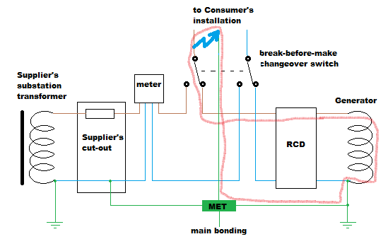
    (and in answer to a couple of other points too). Consider an earth fault in the installation when running on generator. Something like this perhaps (I'm no artist, but blue flash represents the fault and the red smudge the earth fault loop):


    Then plug a few values into Ohm's Law... How much current can the generator provide into a short circuit? The manufacturer should be able to provide an answer, but for simplicity shall we say a simple 100A for the sake of argument? Then the loop impedance - again may vary but for illustration say 0.5Ω - so we have 100x0.5 = 50V difference around the whole loop (the rest of the 230V will be lost internally in the generator). In terms of what's imposed on the DNO's earth terminal - what's the resistance of the loop between the MET (where the DNO connection is) and where the electrode is connected? - say 0.05Ω - so our 100A fault current generates 100x0.05 = 5V difference between the MET and our local true Earth. (Try again with other figures by all means). 5V is likely totally insignificant to the DNOs from a shock point of view, even if all their electrodes were disconnected from your installation and they see the whole of your 5V - they'd often get more than that from other installations whose bonding shares metallic pipework with installations connected to a different substation, and if your RCD is any cop, it'll disappear within a heartbeat or two anyway.  If you moved the connection to your local electrode from the generator's N-PE link to the MET you could reduce or even eliminate even that 5V (or whatever it happens to be).

    In the general case, attempts to "switch off" the DNO's earth often don't work - you'll still need main bonding connected and often enough that means bonding to metallic supply pipework that's shared with  neighbours whose bonding is still connected to the DNO system... so the convention is to leave everything PE solidly connected together. That also removes a possible issue with moving switch contacts being less reliable than a solid joint - you really don't want to loose earthing to an entire installation because of one dodgy switch contact. Your independent earthing facility is independent in the sense that it keeps working perfectly well even if the DNO's facility completely disappears (e.g. because they're disconnected your supply cable) - the general consensus is that there's no need to provide isolation between them (and in the general case you couldn't anyway because your generator earthing would need to be main bonded to your supply pipework which, if shared with neighbours, would connect it directly back to the DNO's earth...)

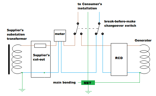
     As above, another option might be to TT both the house and workshop together (one possible way of designing out the problem of having two different earthing systems within reach of each other):


    Where your electrode serves as the consumer's electrode in a TT system when on-grid, and the source electrode in a TN-S system when running on generator. (There would of course be either extra RCDs or careful use of double/reinforced insulation to cover earth fault protection upstream of the first RCD in TT mode, not shown in the above diagram).

    Food for thought perhaps anyway.

      - Andy.

  • Quite so, but is this topic not about low voltage (< 600 V phase to earth AC).

  • So the OP's generator isn't a generator.  And the OP isn't a generator either, because their generator (that isn't a generator) doesn't run at high voltage.

    Simple!

  • Quite so, but is this topic not about low voltage (< 600 V phase to earth AC).

    Indeed ... that means that if you provide generation at 'low voltage' (such as many solar farms on the AC side), you might not be covered by the term 'generator' as defined in ESQCR ... but more pertinent to this discussion, it also means that if you are a 'prosumer' you are also not a 'generator' as far as ESQCR is concerned.