Old MCCBs & MCACBs Data

Good morning all. 

A bit of along shot this one.

Would anyone out there have data on - Maximum permitted Zs values for MCCBs & MCACBs that were fitted in ECC (Electric Construction Company) cubicle boards in the early 1960s? 

Many thanks in advance,

CPC

Parents
  • Breakers to BS 3871 for example, are mostly pensioned off these days, but there is data out there that can be used to decide if the Zs is sensible for continued use. (link to article with figures and some pictures)

    Just to note that they aren't 'measured values', i.e. don't have the 0.8 factor per Appendix 3 of BS 7671, that is used to correct for ambient temperature being lower than cable operating temperature when taking loop impedance readings or measuring (R1+R2). Figures for BS 3871 (max measured, with the 0.8 factor) appear in OSG (Appendix B) and GN 3 (Appendix A).

    Note further, that some tables out there for BS 1361 fuses and BS 3871 circuit-breakers, don't align with the current BS 7671 formulas, for example;

    • some don't include Cmin factor of 0.95
    • some are calculated at U0 of 240 V, not 230 V

    Those tables are quite possibly taken from older guidance, and would have been correct at the time, for earlier versions of BS 7671 / IEE Wiring Regulations

  • Indeed, and a result very close to the pass/fail boundary should trigger some further consideration - with fuses and the thermal part of breakers, the world was simpler, as when checking for a 'must blow in 5 seconds' limit, a marginal answer just meant it would blow anywhere between perhaps 4 and 6 seconds instead  - which is usually within the experimental uncertainly of what matters anyway, as the 5 second figure is itself plucked from the air of convenient round numbers. And the fast blow with fault currents at ten times the rating would vary from 0.2 secs to 0.5, again not perhaps so big a deal. And in an era of re-wireable fuses where so much depends on the tension of the wire, if it is cooled by rubbing the ceramic guides and so on, there was so much slop in the figures that no one would ever know. It just had to be sized well enough to work every time and fuses to blow before cables melt.

    In the same way, exceeding the PSSC was less of an issue - with no contacts to weld, the fusewire always goes open circuit, what varies is if you are just changing the wire, or also sweeping up bits of shattered ceramic out of the holders with a dustpan and brush...


    With a breaker where one is waiting for the near instant magnetic part to operate, except for a few cunning but very expensive designs with hydraulic damping, the magnetic part either fires or it doesn't, so being over the line in the wrong direction could mean the near-instant trip becomes waiting for the thermal part to wake up.
    It is fair to say that it took until the 1990s for regulations and testing practice to catch up.

    Mike
    PS

    Modern breakers are not actually  tested in a way that plots a curve either - its actually a very awkward test to do during manufacture and repeated operation tends to 'life' the mechanism, so only a small sample of  go-no-go cases on either side of the lines are tested to give reasonable confidence that each one is good. Samples from the production line may be taken out and tested to death, but not very often.
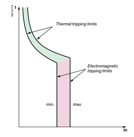
    The curves only represent  the upper and lower limits of accepted performance but their shape is theoretical and based on the likely physics of operation of a near adiabatic operation from the thermal part when faster than a few seconds, and a vertical take off for the magnetic part.
    If you were to test a real breaker and plot the breaking time results on top of the curves you should expect it to meander between the limits, rather than to follow the curve shape exactly.
    The only thing that is sure is that any test to the left of the left limit should be a 'no-go' and any test to the right of the right limit should be a 'go'. Between the lines, well, it may or may not operate, and somewhere in that grey zone it will make the transition from one to the other.
    Mike.

Reply
  • Indeed, and a result very close to the pass/fail boundary should trigger some further consideration - with fuses and the thermal part of breakers, the world was simpler, as when checking for a 'must blow in 5 seconds' limit, a marginal answer just meant it would blow anywhere between perhaps 4 and 6 seconds instead  - which is usually within the experimental uncertainly of what matters anyway, as the 5 second figure is itself plucked from the air of convenient round numbers. And the fast blow with fault currents at ten times the rating would vary from 0.2 secs to 0.5, again not perhaps so big a deal. And in an era of re-wireable fuses where so much depends on the tension of the wire, if it is cooled by rubbing the ceramic guides and so on, there was so much slop in the figures that no one would ever know. It just had to be sized well enough to work every time and fuses to blow before cables melt.

    In the same way, exceeding the PSSC was less of an issue - with no contacts to weld, the fusewire always goes open circuit, what varies is if you are just changing the wire, or also sweeping up bits of shattered ceramic out of the holders with a dustpan and brush...


    With a breaker where one is waiting for the near instant magnetic part to operate, except for a few cunning but very expensive designs with hydraulic damping, the magnetic part either fires or it doesn't, so being over the line in the wrong direction could mean the near-instant trip becomes waiting for the thermal part to wake up.
    It is fair to say that it took until the 1990s for regulations and testing practice to catch up.

    Mike
    PS

    Modern breakers are not actually  tested in a way that plots a curve either - its actually a very awkward test to do during manufacture and repeated operation tends to 'life' the mechanism, so only a small sample of  go-no-go cases on either side of the lines are tested to give reasonable confidence that each one is good. Samples from the production line may be taken out and tested to death, but not very often.
    The curves only represent  the upper and lower limits of accepted performance but their shape is theoretical and based on the likely physics of operation of a near adiabatic operation from the thermal part when faster than a few seconds, and a vertical take off for the magnetic part.
    If you were to test a real breaker and plot the breaking time results on top of the curves you should expect it to meander between the limits, rather than to follow the curve shape exactly.
    The only thing that is sure is that any test to the left of the left limit should be a 'no-go' and any test to the right of the right limit should be a 'go'. Between the lines, well, it may or may not operate, and somewhere in that grey zone it will make the transition from one to the other.
    Mike.

Children
  • Indeed, and a result very close to the pass/fail boundary should trigger some further consideration

    That is perhaps just as much a recommendation because of the accuracy of and resolution of EFLI test instruments (when measuring rather than calculating).

    Accuracy and resolution which makes which is why "rounding up" of a value calculated with the formula OK ... whilst a little more complex, and of course you'd not use a common MFT for such low measurements ... But, it's a good example to point out that  '0.00' is not a valid "limit' for EFLI tests, meaning calculated values must be rounded up to '0.01'. And by the same logic, without going into any complicated mathematics of instrument accuracy, we can conclude that with service accuracies of ± 10 % ± 1 (or more) digit(s) implies rounding test limits up to the nearest '0.01' is correct for an instrument resolution of '0.01', with a known uncertainty of measurement.

    The only thing that is sure is that any test to the left of the left limit should be a 'no-go' and any test to the right of the right limit should be a 'go'. Between the lines, well, it may or may not operate, and somewhere in that grey zone it will make the transition from one to the other.

    Or, continuing the above line of logic, if we are looking at the right hand side as a boundary maximum, it is almost 100 % likely, given a standard distribution curve of products between the two lines (or two arbitrary lines within those lines, that manufacturers will set for their internal quality assurance), that the mcb you have will operate if the instrument reads a maximum as calculated, even it things are "rounded up" by one or two of the last digit ...