TN system for generator

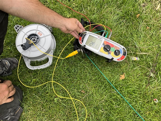
This is the resistance (281 ohms) of the earth electrode connecting star point and frame of a stand alone TPN gen set. It was one of 15 used at a recent outdoor festival. I do appreciate the desire to keep the resistance within the norms usually applied, say around 20 ohms, but I don’t think there is anything in BS7671 that puts numbers on a TN system. I am not looking to debate the merits of such earthing or how this value could be reduced. I guess my question is more concerned about the value of earth resistance that the “T” in TN-S remains legitimate as far as 7671 is concerned. Is it solely related to some value that will ensure RCD protection will operate?
  • Is it solely related to some value that will ensure RCD protection will operate?

    I don't think so. For conventional L-PE faults it has no baring on the matter (as being a TN system the earth fault loop doesn't include the electrode). For faults to true earth (either directly or via a shock victim) the loop impedance is full of unknowns - the resistance of the soil around the fault/victim (likely to be significant - possibly several kΩ) and in the case of shock the body resistance of the victim as well (usually in the 1kΩ ballpark). Additional protection by 30mA RCD should remain effective in any event - if the loop impedance is too high to trip the RCD the current flow will be so small as to have a minimal shock risk - in a way the situation almost degrades to a separated circuit.

    The 20Ω figure for source electrodes comes from BS 7430 I believe, but seems entirely arbitrary - it's the same for a huge system supplying a city block as for a little standalone generator - there's no apparent relationship to the size of the supply, extent of the system supplied or or type of protective device.

    There is one situation where the source electrode value does become significant and that's when your TN system has a TT branch from it (like a TT'd outbuilding from a TN main building with a generator backup) - as it'll directly affect the TT systems loop impedances, and could be a significant problem where higher rated RCDs are used (fault currents could be too low to trip RCDs but still be high enough to be a shock hazard). But as long as you're sure your system won't be feeding a TT'd section, it's not a worry.

       - Andy.

  • My question was really about the first “T” in TN-S, specifically relating to a typical stand alone three-phase generator such as might be used at a festival or other similar event in an open field. 
    For example, does hammering an electrode into the ground and connecting it to the gen set earth terminal (neutral and earth terminal are connected on gen-set start-up) establish the “T” regardless of the electrode resistance (Re)? Or, as I suggested, must it also be reasonably confirmed that the protective device on the gen set will operate on a first fault to true earth, say along the cable feeding the distribution units? That being the case, then it is likely that only a RCD or similar device will be suitable.

    I understand that the first fault to true earth will also have a resistance but how can that be factored in other than to keep Re as low as possible. 
    So when does TN-S become IN-S? 

  • must it also be reasonably confirmed that the protective device on the gen set will operate on a first fault to true earth, say along the cable feeding the distribution units

    I don't think that's possible (because of the lack of control of the loop impedance) nor necessary - unless additional protection is required. Normally double/reinforced insulation (i.e. sheathed cables, suitable for the conditions) suffice.

    So when does TN-S become IN-S? 

    Comparing with an IT system (for which BS 7671 is similarly bereft of useful numbers or means to calculate them) I'd have guess as Rb being sufficiently high that a any shock current via true earth would be insufficient to cause harm - e.g. 23k Ohms to keep shock currents below 10mA. For lower resistances (and so higher potential shock current) ADS on 1st fault would be needed.

       - Andy.

  • This is the resistance (281 ohms) of the earth electrode connecting star point and frame of a stand alone TPN gen set. It was one of 15 used at a recent outdoor festival. I do appreciate the desire to keep the resistance within the norms usually applied, say around 20 ohms, but I don’t think there is anything in BS7671 that puts numbers on a TN system.

    Not that I'm suggesting we can apply a draft standard, but out of interest, the latest Draft for Public Comment for BS 7430 (see here, comments period closes on 10 September) steps away from 20 Ω in cases where generating sets are supplying an installation, and all circuits are protected by RCD, and recommends 200 Ω for TN system (Clause 6.1, Table 1). Where OCPDs are used, the recommendation of Clause 6.1 remains 20 Ω.

    200 Ω is of course provided as a recommendation as above this value it's generally accepted that the earth electrode might not be stable.

    20 Ω is a lot more interesting ... probably the true "source" is legislation and UK supply industry practice, particularly around PME ... interestingly, an earlier value used was 10 Ω.

  • in cases where generating sets are supplying an installation, and all circuits are protected by RCD, and recommends 200 Ω for TN system

    The use of 200 Ω in these circumstances  is not a new concept, and has been used for a number of years in the IET Code of Practice for Electrical Energy Storage Systems, with broad industry buy-in.

  • Thank you GK, at least that gives me some idea of a number. However, it would be a blessing if someone could explain the engineering rationale of the 200 ohms for RCD protected arrangements as distinct from 20 ohms for those without.

  • the engineering rationale of the 200 ohms for RCD protected arrangements as distinct from 20 ohms for those without.

    Maybe I'm being unfair, but my suspicion of the underlying logic would be something along the lines of "20 Ohms can ****** difficult to achieve and isn't really justifiable - while 200 Ohms is a well recognised number (not from any direct electrical calculations, but from a stability across the seasons point of view) and reasonably achievable in the majority of soils ... so what excuse can we come up with to justify a number that's 10x higher than the standard (BS 7430) says...

      - Andy.

  • Well both 20 and 200 ohms seem to be a peculiarly British thing.

    There are a number of real considerations however. One is British soil. If you move to the middle east, or even Malta, the chances of getting anything as low as 20 ohms  with a sensible cluster of electrodes is almost nil. Whereas in the UK in Essex clay it is quite practical to hit 20 ohms with a couple of 4ft rods. Of course where I am in Hampshire, the ground is sand and gravel, and in the recent dry spell a similar 2 rods managed about 300 ohms but ho hum.

    So practically to blow all but the smallest fuse or trip a breaker in any sensible time, relying on a loop with 2 electrodes - one intentional at the genset, and the other accidental at the fault, is a pretty long shot, even for a 5A MCB on a lamp post - which is the sort of thing the 20 ohm figure seems to come from, or rather if 5A is diverted into a 20 ohm electrode, the step voltage is about 100V - and much more than that is getting more than a little dangerous..

    Before my time, I'm told, the way to verify the earth on a TT house was to put a 60W lamp between live and electrode and see how bright it lit. A dim light or no show indicated a bad earth.  So, what sort of value was that checking for ? well a 60W lamp draws 1/4A and is noticeably dim by 200V(?) so if we said 50V dropped at 1/4 amp, that would be about 200 ohms. Hmm. (there are some nasty approximations here, as the filament resistance falls when it is dimmer, but of course the current is not constant.)

    Enter the RCD, now we can have a 'safe' step voltage of say 50V near the electrode at our largest non disconnected fault current  (30mA/100mA or 300mA depending on RCD) so the resistance to terra-firma can be 1.6k ohms /500 ohms or 160 ohms . Well the 160 ohm case needs real electrodes, but the 30mA one will be happy with a screwdriver or a garden fork in the lawn, and now we credibly are protecting the person with wet feet picking up the severed lead to the hedge trimmer or whatever.

    But a high resistance electrode is not good, as if unlucky you can have a fault that is much better earthed than the genset - a live core being spiked by a metal fence comes to mind, and also the falling of a 3 phase connector into a ditch full of muddy water. The 230V is shared between the 2 'electrodes' with the bulk of terra firma at the mid point, and it is possible for the genset and all CPCs to be elevated to most of the supply voltage wrt the ground beneath your feet.

    its arbitrary but worth thinking of the likely fault cases.

    Mike.

  • So practically to blow all but the smallest fuse or trip a breaker in any sensible time, relying on a loop with 2 electrodes - one intentional at the genset, and the other accidental at the fault, is a pretty long shot, even for a 5A MCB on a lamp post - which is the sort of thing the 20 ohm figure seems to come from, or rather if 5A is diverted into a 20 ohm electrode, the step voltage is about 100V - and much more than that is getting more than a little dangerous..

    Agreed, although the discussion is about TN-S, in which the electrode (and the ground it is in) does not partake in the fault path itself for ADS.

    However, for additional protection, the ground and the source earth electrode might be used as a "return". In this case, provided an RCD with residual current rating not exceeding 30 mA is likely to operate, all is good.

    Enter the RCD, now we can have a 'safe' step voltage of say 50V near the electrode at our largest non disconnected fault current  (30mA/100mA or 300mA depending on RCD) so the resistance to terra-firma can be 1.6k ohms /500 ohms or 160 ohms . Well the 160 ohm case needs real electrodes, but the 30mA one will be happy with a screwdriver or a garden fork in the lawn, and now we credibly are protecting the person with wet feet picking up the severed lead to the hedge trimmer or whatever.

    Agreed

    But a high resistance electrode is not good, as if unlucky you can have a fault that is much better earthed than the genset - a live core being spiked by a metal fence comes to mind, and also the falling of a 3 phase connector into a ditch full of muddy water. The 230V is shared between the 2 'electrodes' with the bulk of terra firma at the mid point, and it is possible for the genset and all CPCs to be elevated to most of the supply voltage wrt the ground beneath your feet.

    Also agreed.

    In fact, guidance for some time has been pointing installers away from "earth rod does the job" to the use of earth mat or conductive disc type electrodes for a number of reasons (including reducing the risk of buried services strike, which, in the case of gas, can be very nasty). Having said that, for temporary installations in a field or similar, well, it's going to be some sort of rod isn't it?

  • Having said that, for temporary installations in a field or similar, well, it's going to be some sort of rod isn't it?

    I'd agree for general garden fetes and so on. 
    Or rely  the skids of the genset if the ground is wet, but the sort of scouty event I do, involve so many spikes in the ground, that a few more make no odds to the risk, The sort of things you use to secure a marquee or a climbing tower are probably better electrodes than the official electrodes.

    For some mil stuff we have plates that you drive on that go under the fronts wheel of the vehicle and get pressed into the earth,  these are more popular if there is a risk of buried munitions... some of the stuff I have been involved with  in the past has had some unusual looking risk assessments.

    Mike.