Incomer Protection Requirements where LV cable is direct from transformer?

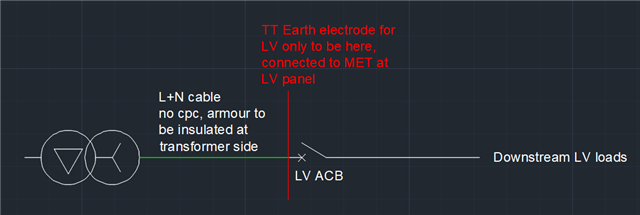
where the LV cable from the transformer is directly terminated at the transformer LV termination box i.e. no circuit protection on the LV take off chamber and feeding into our LV ACB incomer downstream. what is the requirement for circuit protection specification at the LV ACB here? We have been told that the LV earths need to be separate from the HV earth, so we've considered the system to be a TT earth from the LV ACB downstream and will include ground fault settings as an integrated part of the CB specification.

However do we need to consider the cable between transformer and ACB as this would be unprotected and not subject to earth fault as we have no cpc between transformer and ACB panel? is this section of cable subject to any '' IT '' considerations?  

quick sketch to try and make clear what i'm on about :) 

thanks 

Parents
  • thanks Andy - this makes sense, we've been advised that the HV and LV earthing systems must be isolated from each other rather than separate? if this is the case, how would this still mean that the LV side is TN within the green cable section where there is no protective conductor running between transformer and ACB? is it correct to consider that we have a TT earth system at the LV ACB position with this being 'isolated' from the upstream earthing network at the transformer and HV side?

  • To my mind, not TT (you need two separate electrodes, one for the source another for the consumer to make a TT system). Not IT either.

    If the cables are armoured, then the armour forms the c.p.c. Draw out a full diagram - you should still see a complete "fault loop" for a fault between a live conductor and the armour - via the N-PE link (whether it's at the transformer or your panel) - it doesn't really matter that the current has to flow though some conductors that are "downstream" of the fault - as long as the fault current can flow.in a complete loop. The HV fuses (or CBs) should see the fault current (if scaled down by the winding ratio of the transformer) and if it persists long enough, disconnect.

      - Andy.

Reply
  • To my mind, not TT (you need two separate electrodes, one for the source another for the consumer to make a TT system). Not IT either.

    If the cables are armoured, then the armour forms the c.p.c. Draw out a full diagram - you should still see a complete "fault loop" for a fault between a live conductor and the armour - via the N-PE link (whether it's at the transformer or your panel) - it doesn't really matter that the current has to flow though some conductors that are "downstream" of the fault - as long as the fault current can flow.in a complete loop. The HV fuses (or CBs) should see the fault current (if scaled down by the winding ratio of the transformer) and if it persists long enough, disconnect.

      - Andy.

Children
  • ok understood, yep this makes sense when we would still have the amour bonded to earth at both ends . 

    if the transformer end uses a stuffing/insulating gland which seeks to effectively insulate the amour and the armor is then earthed at the LV CB end only which incorporates it's own electrode, then this would be a consumer TT system system right?  

  • then this would be a consumer TT system system right?  

    Sorry!, nope, because there is an NE bond at the LV CB end near where the LV electrode(s) connect(s) , or there really ought to be...

    LV secondary earthing  like this perhaps.

  • ahh yes the N/E link at our switchgear end, thanks for making that clearer !