Definition of high protective conductor currents

I'm currently installing a heat pump and noticed that some of the manufacturer's information says of the RCDs to be used with it:

...now requires the use of a Type B RCD/RCBO with the following specification:

  • Minimum detection capability up to 20 kHz
  • Minimum trip threshold of 150 mA above 1 kHz

and looking at the devices the manufacturer suggests, these seem to be nominally 30mA types.

So it seems to me these suggested devices may trip at 15-30mA at 50Hz, but may tolerate more than 150mA above 1kHz.

My first thought was where does this leave me with respect to section 543.7 (equipment having high protective conductor currents)? Can I assume that the 10mA limit only applies to 50Hz currents? or given the way the words are written should it be read as applying to all frequencies?

The other (possibly more important question) is how do currents at higher frequencies affect the human body - if I have a device that maybe doesn't trip until over 150mA (at 1kHz) do I still have additional protection? I think I recall that 50 or 60Hz is about the worst possible choice of frequency for shock considerations, but can currents at higher frequencies be safely ignored entirely?

I guess similar considerations might potentially arise anywhere we have power inverters .. so my heat pump might be just the tip of the iceberg,

   - Andy.
  • ensure my setup complies with 543.7...

    A sensible precautionary approach.

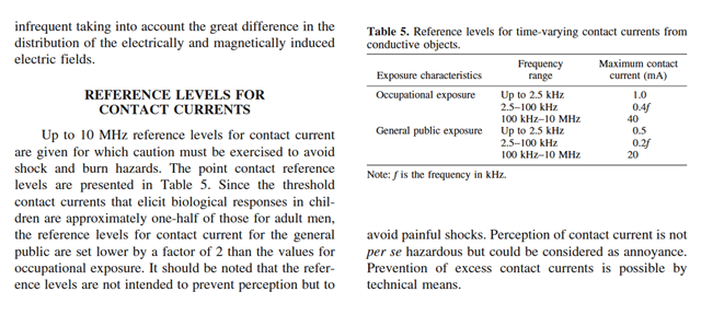
    I notice Mike's graph is based on pain rather than effects that cause permanent damage or Ventricular fibrillation, so maybe there's still a bit of room for debate

    Oddly its not an area that most folk are keen to research and there is not a lot out there  !!

    This from ICNIRP may be of interest to you. 

    GUIDELINES FOR LIMITING EXPOSURE TO TIME-VARYING ELECTRIC AND MAGNETIC FIELDS (1 Hz TO 100 kHz)

    While predominantly about radiation, it does cover direct contact as well.

    Note however that the numbers here are a factor of 30 or so lower than those used by BS7671 and the standards from which it derives its specifications... And, given results of rather worryingly simple/ dangerous tests like this, perhaps correctly so.

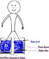
    https://pmc.ncbi.nlm.nih.gov/articles/PMC2763825/ scroll down to the rather childish picture of someone with feet in two buckets of water.

    Fresh (not salt) water with conductivity of 320 µmho/cm filled each bucket to a level near the hip. It was found that electrically induced muscle contractions were greatly modified by leg position in the water.

    Initial testing has shown that with 3.05 V (60-Hz AC rms) applied between the plates, a current of 8.65 mA flowed, resulting in involuntary flexion of the knee to 90°. This flexion could not be overcome with voluntary effort. ..

    Now that's a voltage most regulation writers feel is safe, even near a swimming pool  ;-)


    Then there are folk measuring people and arguing the existing body resistance model is wrong (well, more charitably, incomplete perhaps)

    Assessment of Human Body Impedance for Safety Requirements Against Contact Currents for Frequencies up to 110 MHz

    It is fair to say, the science is not settled. I'd prefer screened or armoured  cables for now.

    Mike.

  • DC-DC converter stage with HF separating transformer, between rectified AC input, and inverter output, 

    Yes, and that sort of thing may well happen outside the R & D labs eventually (currently its still in the long haired 'too hard to be worth it' pile I think )
    It will still bring some primary side earth current problems similar to those in the average EV, that more  or less does the first step  of this already. However MF  transformers that allow the core and inter-winding foils that connect to the primary DC help significantly by breaking the capacitive path between primary and earth referenced secondary..

    Once cost - effective semiconductors and magnetic materials allow that sort of power level, then at about the same time we may also see a move to get rid of some of the mechanical tap switching and 50Hz transformers at smaller substations where power levels to be switched are comparable.

    Mike.

  • Thanks guys - this has been very useful!

    I notice Mike's graph is based on pain rather than effects that cause permanent damage or Ventricular fibrillation, so maybe there's still a bit of room for debate there (I'm sure I recall a 400Hz system for aircraft that was meant to have a reduced shock risk). But all the same we still have no solid evidence that higher frequencies can be safely ignored.

    For me that calls into question the effectiveness of specifying 30mA RCDs for additional protection in this case. I guess in the case of direct contact with live conductors on the a.c. supply side the residual current will still be 50Hz and so the RCD should trip as normal. But for other cases - e.g. a broken c.p.c. (single fault) the current flowing from the equipment case via a victim could well have high frequency high current components the RCD would ignore, but could still prove fatal. So my first question - whether we should have high integrity c.p.c.s seems justified,

    Or just design out the need for a RCD of any kind

    Indeed - that was my starting point. I've still got an open question with the manufacturers whether their statement that ALL the heat pumps need an B-HP type RCD should be read as requiring RCD protection where BS 7671 makes no such demands - or whether they just meant "where an RCD is present it shall be a B-HP type".

    Given the supply wiring is fixed, unlikely to be damaged and everything else is contained within an earthed metal box, the need for additional protection seems very small.

    In the mean time I'll be looking to ensure my setup complies with 543.7...

       - Andy.

  • Perhaps another approach could be to use a DC-DC converter stage with HF separating transformer, between rectified AC input, and inverter output, to provide the separation, and drastically reducing the impact of providing separation on losses, cost and weight!

    Or just design out the need for a RCD of any kind. Appropriate design would negate the need for RCD protection on TN systems or additional protection on TT systems. 

  • And of course its not the maker's problem to say 'use an RCD as required by local regulations',

    I'm led to understand some inverters (e.g. heat pumps) need an RCD with a performance that doesn't yet have a classification in standards (but does exist in the market place).

    On top of that, the cost of even a standard Type B is an issue of cost to someone, as well as the fact that it may also use power (but that may well be less than the losses of a transformer).

    Very true, but to a manufacturer, quite undesirable for a number of reasons. The obvious penalties are size and weight, although that only increases manufacturing, materials, storage, and shipment costs. Then there is also a problem in terms of selling the efficiency ratings to the user (not just explaining an increased floor or height claim) for reasons of transformer losses once in use - its an extra few % of the kVA going as heat that has to go somewhere - trivial if its a few % of less than a kilowatt, but actually really awkward once you get to  using VSDs that are ten times that or higher. 

    Perhaps another approach could be to use a DC-DC converter stage with HF separating transformer, between rectified AC input, and inverter output, to provide the separation, and drastically reducing the impact of providing separation on losses, cost and weight!

  • That is to use a transformer with simple separation.

    Very true, but to a manufacturer, quite undesirable for a number of reasons. The obvious penalties are size and weight, although that only increases manufacturing, materials, storage, and shipment costs. Then there is also a problem in terms of selling the efficiency ratings to the user (not just explaining an increased floor or height claim) for reasons of transformer losses once in use - its an extra few % of the kVA going as heat that has to go somewhere - trivial if its a few % of less than a kilowatt, but actually really awkward once you get to  using VSDs that are ten times that or higher. 

    It is for the same reasons that it is now almost impossible to buy any domestic appliance that does not contain a switch mode supply of some kind - and the UKCA/ CE efficiency requirements have all but removed traditional linear power supplies even from the small 'wall-wart' applications, so the modern house is buzzing with RFI generating switchers.


    And of course its not the maker's problem to say 'use an RCD as required by local regulations', however unhelpful it may be to us, it's very easy for them, the extra ink in the handbook is almost free.

    So while the transformer idea is technically appealing, and personally I'd love it , I'm not holding my breath for many makers to adopt it.
    Mike.

  • There is another approach which completely removes the issue, localising earth leakage to the heat pump itself. That is to use a transformer with simple separation.

    Example for single-phase in Figure 12.4 (p104) of GN5.

    If manufacturers built that into the heat pump, or used an inverter with separation (possibly cheaper transformer like in a DC SMPSU), no special precautions are necessary in the installation.

  • After posting, I did some extra web searching, as you do ;-) 

    I found a quite good tech note from Schaffner on the RS web site that provides a good bit of background (and slightly slides past other nuance aspects) on Low Leakage current EMC filters with full RCD compatibility   I Also found Hager's "Why Use Type B HP RCDs for Heat Pump Applications" which has comments about the VDE B+ standard.

    The main clue is it's the "Type B" problem of anything with switch mode electronic loads which [could] effectively create (on an average, 20ms cycle) a DC load through the residual/leakage sensing coils. The 'could' part is that most of the current is very high speed switching transients, which if not internally filtered in the circuit breaker device look like live leakage (up to a point where the equipment needs to filter as well, no doubt also for RFI reasons). 

    The nuance bit that I hadn't implicitly realised is that the electronic device's diode rectifier, and capacitor, has a store and delay effect on the way supply current is converted to leakage current, such that from the supply side the leakage is in phase (goes through the expected rectifier phase diodes), but on the load side it is, on average, DC.

    The Schaffner fig 1 shows the leakage paths. Diag 4 shows the RCD tripping, diag 6 shows a situation where the equipment switching currents are too high (without filter, labels in German;-) and then diag 7how their filter saves the day on the equipment side and stops nuisance tripping relative to a type B RCD..

  • The other (possibly more important question) is how do currents at higher frequencies affect the human body

    Afraid that all this talk of various frequencies makes my eyes glaze over, but v. high frequencies are used in diathermy. Bipolar is easy to understand - the current passes between the tips of a pair of forceps and cooks the tissue, which stops any bleeding. Rather more old-fashioned monopolar diathermy has a large "earth" plate attached e.g. to a buttock where the current density is low, and a pointy instrument where the current density is high, and accordingly, able to coagulate (stop bleeding) or cut.

    Then you have things like cardioablation, where the electrode is poked into yer heart tissue and the current fries it, so clearly HF currents can have very beneficial effects. :-)

  • Certainly the leakage current from a switch mode power supply is far from simply sinusoidal and contains pulses of both polarities that may be only 10s of micoseconds apart and of very short duration (sub microsecond). If you average these over the period of a half sinewave at 50Hz, you measure a very low residual, as the ups are cancelled by the downs and furthere more, for say 90% of the time there is nothing there at all....  A traditional mechanical balance trip RCD sort of did this for free as the short spiky pulses simply could not get the armature moving, giving a natural low-pass (HF reject) effect.
    A first generation electronic RCD however uses a comparator that on-chip has transistors that certainly can change state at the same sort of speeds as those in the SMPS, actually faster probably, being as large power devices are slower due to increased transit times than the smaller devices on-chip.

    Therefore there has to be a deliberate low pass filtering added between the sense coil and the comparator/ amplifier to roll-off the unwanted response to those sharp spikes, to make the RCD behave more calmly and in a similar way to a good old mechanical trip.
    This expectation of a roll-off by 5 (about 16dB) between 50Hz and 1kHz is an attempt to  recognize and accommodate the sort of filtering needed to avoid tripping out when things are actually working as they should. It also helps to reduce the mis-firing on other one shot transients such as arcing light switches.

    There is a certain irony that in an AFDD that high frequency sensitivity has to be build back in, but then tamed by a multiple 'if this and that but only when this happens too' type of algorithm and of course sensing the line as well as the  imbalance currents.
    Mike.