DC Cabling Current Carrying Capacity - Continuous vs Momentary / Finite Period Assessments Query

Hi There, I have a somewhat delicate design predicament in connection with the above.

There is an existing UPS installation in a UK data centre which is to be upgraded. In amongst a few other design elements this involves the calculation of dc cabling circuits from UPS to Battery Panels and Battery Panels to Battery Strings. The client scope is simply to replicate existing with any additional elements to be added / upgraded but on modelling such, utilising site specific details and BS7671 calc requirements, there appears to be cable undersizing shortfalls on both of the aforementioned existing dc cabling circuits.

When this is advised to the client they then approached the D&B installer of the original system and put simply the installer has said that with UPS systems, where the load is momentary and for a finite period, together with temperature rise factoring, alternate calculations can be provided which allow higher load currents to pass for designated short time periods. Such calculations are not derived from BS7671 as it cannot apply due to any current carrying capacity calculations being based upon continuous loading. They also note that grouping de-rating factors need not apply.

When I have asked the installer to substantiate their calculation view they have noted 2no. documents, namely IEC 60092-352 and a technical handbook document developed by Siemens Germany. My initial challenge is that the latter IEC document relates to electrical cabling systems on ships and the Siemens handbook was initially compiled in 1987 and was seemingly last updated in 1990, so it's over 35 yrs old. The handbook is not available via any Siemens website and it also heavily refers to German DIN VDE standards.

I cannot see how I can consider the installers calculations as valid as they are substantiated by an IEC document that clearly does not apply to a traditional building installation or a handbook which could be out of date and therefore no longer relevant.

I have researched the momentary load / finite period premise online, I can appreciate the premise, but whilst I can find some vague technical papers partly relating I can find nothing up-to-date to support such, nor am I aware of anything within BS7671 that allows such extended current carrying capacities based upon cables for shorter periods.

I would very much appreciate any opinion or guidance on the foregoing!
Parents
  • Well, firstly the tables in the annexes to BS 7671 are all relating to very specific installation assumptions  - and therefore implied assumptions about airflow and conduction of heat to the environs (itself at particular temperature), and also to steady state loading. Inrush current of up to ten times the steady state rating is common in some motor start applications.
    The tables are there to allow the safe and conservative design of systems that do not exist, so that they definitely run at acceptable temperatures and should give no problems with an estimated 70 year lifespan.

    Of course you already have a system, that I hope you would have mentioned if it was suffering signs of thermal distress, so presumably there are factors in this installation that help it along.  So there are some questions - is the air temp controlled in your facility, what is the design load duty cycle, what is the longest burst on time, and what is the design life of the installation.

    Note that cables (but not perhaps the things at the ends of them) can be run quite a lot hotter than the 70C core temperature, but the lifespan shortens from decades to years, roughly halving with every 8 degree rise.

    In terms of time constants - things can warm up quite slowly as illustrated here.

    https://electrical.theiet.org/media/1704/establishing-current-ratings-for-cables-in-thermal-insulation.pdf

    Mike

    PS

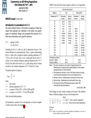
    When you do overload a cable... the power dissipated is equal to P=I²R, so the temperature rise increases roughly in line with the square of the current*, so assuming you have a cable rated at 27A and its running at 70 degrees copper temp (yeah, just assume), the temperature rise normally is 40 degrees (from an ambient air of 30), say you put a load of 32A on this cable, that's an overload of factor 32/27 = 1.185, the temperature rise in this case will be (1.185)²x40=56.2 add that to the 30 start point and you get a conductor temperature of 86 degrees which won't start any fires, but the lifetime of PVC cable halves for each 8 degrees its overrun, so pvc cable run 24/7 at its tabulated rating lasts 23 years, this one only lasts 23/4 = 5.75 years before it starts to crack, very few installations  run their circuits at full load 24/7 though.

    Now if you have that the load for only 8 hours a day the expected life time for the cable at its tabulated rating is 69 years.

    Even if you did put a 10.8kw shower on the end of the 27A cable, I'm not sure any fires would start... the ageing rule breaks down at about 120 degrees when the cores start to melt through the PVC and things tend to go bang... and this is quite a way off the 451F/233C point at which even paper paper catches light  ! (With a nod to Ray Bradbury)

    *We assume that the rate at which a cable can shed heat into the surroundings doesn't go up as the temperature difference between the cable and surroundings increases, which is not really correct, but I'm not sure quite how it changes and I see no reason to complicate the numbers further

    some of the figures are taken from an IET  paper dealing with thermal ageing that used to be available at 
    http://www.iee.org/Publish/WireRegs/Commentary-UpdateApr04.pdf - sadly its gone in one of the website re-shuffles. so here is a copy ;-)
    PDF

  • Is the "attached pdf" just 2 pages on a single sheet? engx.theiet.org/cfs-file/__key/communityserver-discussions-components-files/4/Commentary_2D00_UpdateApr04.pdf

Reply Children
  • yes - the standard it is lifted from is/was IEC 943, but now subsumed by the more recent

    IEC 60943.Guidance concerning the permissible temperature rise for parts of electrical equipment in particular for terminals. 

    The technical approach (and numbers)  remain essentially the same, but its almost 60 pages and about £300 more than the free PDF ;-) 

    Mike.