Group 1 Medical location – supplementary equipotential bonding within the room

The following questions related to how the supplementary equipotential bonding, is arranged with a typical Group 1 medical location room.

The attached sketch is provided to provide a visual representation of the Questions raised.

All questions relate to this element: 710.413.1.6.1 states that: In each medical location of group 1 and group 2, supplementary equipotential bonding conductors shall be installed and connected to the equipotential bonding bus bar for the purpose of equalizing potential differences between the following parts, located in the "patient environment": – protective conductors; – extraneous-conductive-parts;

Question 1 Conductive parts in the ceiling void

If metal pipework and ductwork is located in the ceiling void, but does not drop down to serve an outlet or appliance with the room, the patient environment’, do these services need to be provided with supplementary equipotential bonding?

Question 2 – False ceiling support grid

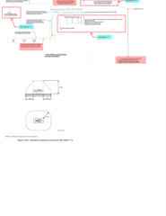
The patient zone defined in Figure 710A – Example of patient environment (IEC 60601-1), shows that 2.5m from floor to ceiling is defined as the patient environment, (however the 2.5m dimension is not prescriptive).

In a typical room if the ceiling grid is more than 2.5m above finished floor level, then can it be taken that it is outside the patient environment and does not require supplementary equipotential bonding?

Also, what defines the 2.5m, rooms of this type are typically 2.4m above finished floor level, as I would consider that could be deemed to be outside the ‘patient environment’?

Question 3 – Luminaires recessed into or fixed to the ceiling void

If the luminaires to the room are recessed, or surface within the room, and are not within the ‘patient environment’ is there a need to provide supplementary equipotential bonding? If the light switch that controls those luminaires falls within the ‘patient environment’ does that mean, the light switch should be bonded?

Question 4 – Supplementary equipotential bonding of general power circuits

PDF For the bonding a general power circuit, is it required only to provide a bonding cable from the equipotential earth bar to the first socket outlet, as it is assumed the remaining general power outlets will be bonded together by the circuit’s earthing cable?

Parents
  • Simon, your numbering suggests that you may be looking at an older version of BS 7671 than 2018+A2:2022.

    710.415.2.1 In each medical location of Group 1 and Group 2, supplementary protective equipotential bonding shall be installed ... for the purpose of equalising potential differences between the following parts, which are located or that may be moved into the 'patient environment': ... (my emphasis).

    The patient environment is not the whole room. "Patient environment" is defined in Part 2 and (in the same words) in BS EN 60601-1:2006+A13:2024 at paragraph 3.79. As you say it is shown diagrammatically (Fig 710.1 in BS 7671 and Fig A.9 in BS EN 60601).

    The dashed line in the diagram does not go through the ceiling (or floor) so I conclude that anything in the cealing void is not in the patient environment and accordingly, does not need to be bonded.

    Q4: I think, yes. Fig 710.2 has the bonding conductor joining the protective earth between two sockets.

    I shall think about Q3 over dinner.

  • Q4: My view is whilst there should be a direct bond from the EBB to the power circuit - which the point of connection is likely to at the socket outlet back box - the rest of that circuit should already be bonded together by nature of the circuit's CPC.

    However as the overriding factor being no exceedance of the 0.2 Ω from the terminals for the protective conductor of socket-outlets
    and of fixed equipment or any extraneous-conductive-parts and the equipotential bonding bus bar - it is likely that the bonding between the sockets is to provide certainty as opposed to necessity. 

  • and, critically, to make sure that if any fault does put current into the earth, for the half a second before something trips, the voltages all rise as one, rather than the cases of things connected to  the CPC of one circuit briefly being tens of volts apart from the rest of the kit. The key thing here being 'equipotential' between the simultaneously in contact,  rather than  holding to any particular local or remote value of 'zero' volts.

    Actually, unless the PSCC is very low, 0.2 ohms is likely to involve quite an uplift in voltage, but that limit has more to do with what you can easily measure for verification with low current meters than any particular rise of earth potential.
    Mike.

Reply
  • and, critically, to make sure that if any fault does put current into the earth, for the half a second before something trips, the voltages all rise as one, rather than the cases of things connected to  the CPC of one circuit briefly being tens of volts apart from the rest of the kit. The key thing here being 'equipotential' between the simultaneously in contact,  rather than  holding to any particular local or remote value of 'zero' volts.

    Actually, unless the PSCC is very low, 0.2 ohms is likely to involve quite an uplift in voltage, but that limit has more to do with what you can easily measure for verification with low current meters than any particular rise of earth potential.
    Mike.

Children
No Data