Unfused Spurs from a Ring Circuit

I am not an electrician but have electrical knowledge and some knowledge of ring circuits and the wiring regulations. I would like to understand from expert readers some points about an unfused spur from a ring circuit.

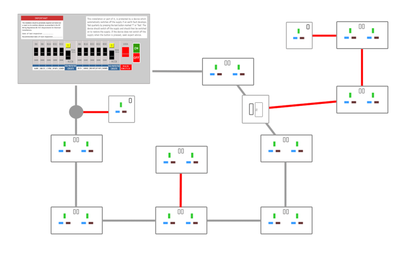
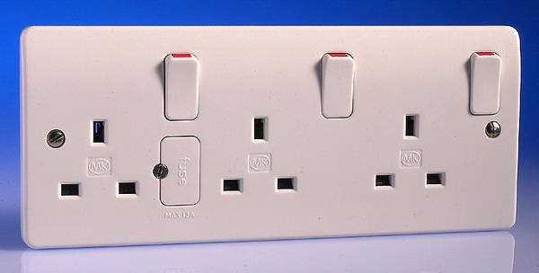
As I understand it the regs say that an unfused spur in 2.5mm cable from the ring circuit may feed only one single or twin (or triple?) socket OR one fixed appliance via a Fused Connection Unit (FCU).

BUT if instead of feeding a single fixed appliance, that FCU fed several sockets, would such an arrangement comply with the regulations. The combined maximum current to those sockets would of course be limited by the FCU 13 amp fuse and RCD protection is assumed at the Consumer Unit.

This limited current capability of sockets fed in this way might be restrictive, but might be OK if low current loads are connected to them e.g TVs, computer power supplies, electric armchairs etc.

I would like to understand if such an arrangement would be feasible before I call in a qualified electrician to quote for it. The reason for asking is that it would allow the provision of surface mounted sockets thus avoiding the need for disruptive cable chases in the wall.

Thanks for any feedback you may offer

Parents
  • yes. You may supply an unlimited no of sockets through a fused spur.
    However I suspect most sparks would rather open the ring and extend that, as the 'small loads only' assumption may not be met in future.

    The 'top right' on the diagram below.


    edit  PS a triple socket has a single 13A fuse built in, covering all 3 sockets. so is an example of what you are considering anyway, just with the shortest possible length between sockets and  the fuse.


    Mike.

  • Thank you for your reply. I understand your point about future demand of the sockets. Extending the ring might ne disruptive. Should I assume that electricians would be wary of implementing such an arrangement as I have described.

    Re your diagram, thanks for that. It's slightly different to what I had envisaged because the FCU is connected in the ring and not at the end of an unfused spur cable.

    Thanks for the MK pic. I'd seen those. If this was connected at the end of the unfused spur cable would the onboard fuse effectively act as the "FCU"

  • Yup. 'wary' covers it !!

    you can put the triple socket at the end of an unfused spur, because the total current is limited by the fuse, the end at which the limiting occurs is not so important, so long as if there were ever  damage to the cable supplying it can cleanly blow the upstream protection (rather than just catch light and blow nothing. )

    In this case upstream is the breaker at the consumer unit. So a very thin cable with a 1A fuse on the end of it from a 30A supply  would probably not be OK, but a 2.5mm2 with a 13A fuse at the load end, supplied from  30 (or even a 40A) breaker would be.

    Sometimes you also see unfused spurs of higher loading but wired to the ring in 4mm2, but that is not a standard arrangement, and is not good, if that load is very near one end of the ring, so the clockwise anti-clockwise split is uneven (which of course depends on the relative lengths==resistances of the 2 possible current paths)

    Mike, 

Reply
  • Yup. 'wary' covers it !!

    you can put the triple socket at the end of an unfused spur, because the total current is limited by the fuse, the end at which the limiting occurs is not so important, so long as if there were ever  damage to the cable supplying it can cleanly blow the upstream protection (rather than just catch light and blow nothing. )

    In this case upstream is the breaker at the consumer unit. So a very thin cable with a 1A fuse on the end of it from a 30A supply  would probably not be OK, but a 2.5mm2 with a 13A fuse at the load end, supplied from  30 (or even a 40A) breaker would be.

    Sometimes you also see unfused spurs of higher loading but wired to the ring in 4mm2, but that is not a standard arrangement, and is not good, if that load is very near one end of the ring, so the clockwise anti-clockwise split is uneven (which of course depends on the relative lengths==resistances of the 2 possible current paths)

    Mike, 

Children
No Data