Siemens Isolating Transformer

Good Afternoon Everyone, I have a question which Im getting conflicting information about and would appreciate the advice.

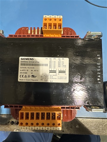
I have a Siemens Transformer model number 4AM6542-8DD40-0FA0 Ive attached photos of the transformer itself. 
My input supply L1-L2 measured 427 volts and I require a 230 volt output 

can some please shed some light on whether or not I need links and how to connect to this transformer. My understanding so far is 1 and 8 input then connect external link across 3 and 6, some people are saying to connect input to 3&6 

secondary side connected to 31&34 and then link 32 to 33. 
34 being the neutral output which will share 0v neutral and CPC/Earth 

Many Thanks In advance 

  • Yup - in some ways the labelling could have been clearer by being the right way up. 

    The circuit is your friend.

    There are 2 windings of 115V  or so, 31- 33 and 32-34. They need to be in series for your 230V winding.(link 32-33 - that is the centre tap, and define one or other of 31 or 34 as live, and the other (34 or 31) as CPC/neutral. Unless you wanted centre earth then you earth the middle and have 2 lives.. )

    The 427 V side will be the other two windings joined in series but not the full length. (full length is both in series is 550V so you need to not use about 20% of fit.) These two windings are neither identical lengths nor identically tapped, so the combinations are a bit eclectic. Rather your 2 phases come in on 1 and 8, and you link either 3 to 6 (~ 440V) or 3 to 7 (415V)  to use 3/4 of winding one, and a few extra turns from winding 2. Personally I'd start with 3-6 linked - having more turns rather than less for the supply voltage will reduce the risk of core saturation (for any give core size and material there is a maximum volts per turn / minimum turns per volt. Exceed this and at best it runs hot, and at worst it self destructs. ) Far safer to approach from below, and have a 230V output that is a volt or 2 under the bar.

    Once it is running you can asses if it needs a tap change or use a meter to work out the actual tap voltages and therefore the % change on the other side.

    If this makes no sense, come back and I can try again.

    regards Mike
    edited for grammer.

  • Amazing, This is exactly what I was thinking. So to confirm the following 

    1 - L1 input

    2

    3 - Link

    4

    5

    6 - Link

    7

    8 - L2 input

    31 - Live 230v output

    32 - Link

    33 - Link

    34 - Neutral and CPC to outgoing circuit

  • yes that would be my preferred safe starting point, then see with a meter if it's good enough for your purposes.

    if its not, note the voltages on all the primary tap points counting up from 1 - 8 and come back if you cannot see what you need.

    Mike

    PS edit approx voltages of winding segments estimated from simultaneous equations. 
    First winding 
    1-2 175 volts

    2-3 35V  (so 1-3 is 208)

    2-4 22V  (so 1-4 is 230)

    Second winding 

    5-6 is 80V (so 5-8 is 350V )

    6-7 is 22V ( so 6-8 is 230V)

    7-8 is 208V


    and 208 (1-3 )+ 230 (6-8) is 438, so perhaps slightly higher than ideal but the available steps are quite course,