
How good are you at telling the difference?
How good are you at telling the difference?
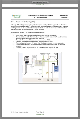
My understanding is that the TN-C-S(PNB) earthing arrangement is installed by the DNO to provide a minimum of 8.000 metres separation between the transformer HV earth system and LV earthing system provided for the customer by the DNO.

My understanding is that the TN-C-S(PNB) earthing arrangement is installed by the DNO to provide a minimum of 8.000 metres separation between the transformer HV earth system and LV earthing system provided for the customer by the DNO.
Agreed ... but there are two variations
- one in which the system is earthed at one point only (at or before the first customer, typically of a maximum of 4 customers). This, however, is still NOT TN-S.
- one in which the system is earthed at or close to each customer's premises (again typically no more than 4 customers). In this case, the N-PE siplt is often at the customer's premises.
Whilst one variant of PNB is closer to TN-S than PME, I'm sure it's not correct to term it 'TN-S'.
TN-C and TN-C-S systems come in more variants than 'PME'

My understanding is that the TN-C-S(PNB) earthing arrangement is installed by the DNO to provide a minimum of 8.000 metres separation between the transformer HV earth system and LV earthing system
From my occasional gazing at rural distribution systems I think it's quite common to have the (first) LV earth "one span" away from the transformer - as with HV overheads (what we used to call "hot" sites) the LV earth needs to be kept separate from HV earth regardless. I'm sure I've seen it on what must be PME on the LV side (as it feeds >>4 customers).
My understanding was PNB was used where there really wasn't really the space to have multiple electrodes on the LV side (e.g. one span away from the transformer is the house). Of course it then gets extended when another house gets built next door... then it gets a lot messier.
- Andy.
I'm sure I've seen it on what must be PME on the LV side (as it feeds >>4 customers).
Agreed, that would normally be done to full PME requirements.
My understanding was PNB was used where there really wasn't really the space to have multiple electrodes on the LV side (e.g. one span away from the transformer is the house). Of course it then gets extended when another house gets built next door... then it gets a lot messier.
The original purpose was where there's pole-mounted transformer (HV to LV), and the transformer's HV earth is at the pole. Under these circumstances, it's rare that the conditions to combine HV and LV earths are met, so the LV earth has to be separated from the HV earth according to the relevant standards (see BS EN IEC 61936-1 and BS EN 50522 for the relevant conditions and requirements). Typically, as Chris Pearson stated, the separation distance between HV and LV electrodes is at least 8 m.

Typically, as Chris Pearson stated, the separation distance between HV and LV electrodes is at least 8 m.
Who? Not me, Gov.
However, Stepdaughter's previous semi-detached cottage is supplied from a pole transformer, which appears to be earthed on the LV side a few metres away.
The supply is 2-wire aerial. It may at one time have supplied just the one house on that side of the road, but at some stage, the barn was split off to became in due course Stepdaughter's house.
Of course it then gets extended when another house gets built next door... then it gets a lot messier.
Exactly!
The thing is that the service head has a PME link, but there appears to be no further earth. The lines do continue where they supply lighting down a private drive, but with no obvious distant earth.
They now live adjacent to the field with the transformer, but the supply is underground - God knows what lurks there! In any event, the service head has a N-PE link. I know 'cos I have seen it.
Who? Not me, Gov.
Sorry, it was Sparkingchip 
Wouldn't mind, but I've not even had a beer or glass of wine yet !
The thing is that the service head has a PME link, but there appears to be no further earth. The lines do continue where they supply lighting down a private drive, but with no obvious distant earth.
They now live adjacent to the field with the transformer, but the supply is underground - God knows what lurks there! In any event, the service head has a N-PE link. I know 'cos I have seen it.
So the point here, is that if the second property has extraneous-conductive-parts, the neutral is now effectively multiple-earthed. It's still probably not PME, but it's certainly not TN-S either.
My sister's house is similar ... it has a DNO-provided earth electrode, but I don't think they maintain that?

That offset electrode arrangement is common with pole-pig installations in Hants and Wilts too, for the same reason, that a low enough resistance to consider it a 'cold' site and combine the earths is almost impossible to maintain.
The transformer pole (or poles if it is a cross-bar 'H' style) has the HV electrode at the base, and that earths the transformer tank, core and possibly bits of support metalwork, and is there to trip the earth fault detection at the other end of the 11 or 33kV. much as if a line had come down.
The bit of the ABC that is between transformer star and the LV electrodes is not really 'combining N and E functions in a consumer installation' , but it is important to see that cutting it does not have the same effect as cutting the equivalent conductor much beyond the first electrode. It does still unbalance the phases, and, as there is now nothing to pull down on the inter-winding capacitance, the 3 phase bundle can float up to some very nasty divided HV quantity, but on the other hand the earth and neutral do not become dangerous
There is a reason that where used to be is 4 bare singles, Aerial Bundle Cable is slowly replacing it - far better for all cores to break when a tree comes down, rather than just the one that leaves the rest alive.
Mike.
and, as there is now nothing to pull down on the inter-winding capacitance, the 3 phase bundle can float up to some very nasty divided HV quantity,
I wonder if it's quite as bad a that - after all the L side of the winding is still referenced, via connected loads, to Earth - not quite the referencing anyone would want, but still not really left to float entirely (at least not until someone turns everything off...)
- Andy.
We're about to take you to the IET registration website. Don't worry though, you'll be sent straight back to the community after completing the registration.
Continue to the IET registration site