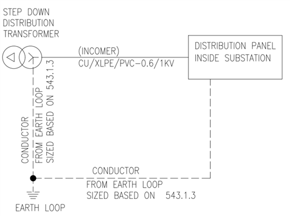
Does the earthing arrangement as per below image considered violation for section 543.6.1
Does the earthing arrangement as per below image considered violation for section 543.6.1
I'm not sure about the "size based on 543.1.3" - while it certainly needs to meet adiabatic requirements there are a lot of other things that might need to be considered too - e.g. if its buried, shared with HV earthing, possibly PME requirements and so on - let alone overall loop impedance values - any of which might require a larger size.
As for 543.6.1 - that's all about the physical separation of the conductors - loops formed around large areas won't cancel magnetic fields anything like as readily resulting in higher loop impedances than would be the case if the conductors were run close together - especially with very high currents (as you get during faults). The same logic that prefers trefoil arrangements of large singles. The actual distances are rather a matter of scale - where centimetres or less might be reasonable on a small circuit, several metres might be a more reasonable in a huge sub-station.
It's all a bit of imperfect science in any event - often parallel paths mean that earth fault currents are split and take a myriad of different routes, so chances are the c.p.c. current doesn't cancel things out fully anyway.
- Andy.

I interpreted the question rather differently.
Perhaps it comes back to the earthing system discussion once again?
For me, the question is whether the bottom right "earth loop" is incorporated in the same wiring system as the live conductors or is in their immediate proximity.
So, what is immediate proximity?
The world snooker is on right now, so it puts me in mind of replacing a colour when its spot is occupied. The ball must go as near as possible in a straight line above the spot without touching another ball. That is immediate proximity.
I would say that immediate proximity would be in the same containment system or support so that it is clear that the PE is associated with the live conductors. That said, I think that more info is required.
The main question, for example, there is a transformer at one side of building and foundation earth loop around the building, if the distribution board is another side of the building and far let's say 50m from transformer, can I connect the PE conductor directly to the earth loop beneath the MDB or I shall wire it back to the transformer on the same route of Incomer cables?
If I understand correctly, and that is always a bit uncertain, it sounds rather like you have some kind of a foundation earth electrode that is distributed, and at least two points of connection to it, and want to use it as the sole CPC ?
The answer to that is a resounding ' only sometimes it maybe OK' !
It all rather depends on the construction of that foundation electrode and any joints in the current paths through and around it. Realize that during fault you don't want a combination of currents and resistances that gives any significant voltage slope across the floor of the building from one side to the other.
For example I'd be very wary of using two emerging bits of rebar from opposite corners of a floor slab for a high PSSC if the grids and bars are only connected by rusty twist wires. (thought those two connection points may well be provided this is to allow the connections below ground to be verified - that's hard to verify with a single point connection as you cannot be sure if half the electrode has rotted and gone high resistance or not. )
However a continuous welded copper tape buried in the manner of a lighting conductor may be much more reliable than a cable.
The preferable approach, if there is any doubt at all, would be to connect to the foundation electrodes at both location but not to rely on that as the sole connection and to have either a dedicated CPC along side the feed cables, or to use the conduit or ducting that they are carried in as that CPC, if the steel or whatever cross-sections work out for the expected fault currents.
Mike.
We're about to take you to the IET registration website. Don't worry though, you'll be sent straight back to the community after completing the registration.
Continue to the IET registration site
