Simultaenous Contact

Good afternoon all, 

I am seeking the collective views of the group regarding the issues we are currently encountering within the EV installation environment in relation to simultaneous contact.

In simple terms, we are seeing a significant number of installations where customers have lamp posts located within their driveways. In many of these cases, it is not possible to achieve the recommended 2.5‑metre separation distance.

My position is that, where physical separation cannot be achieved, the application of layered protection at the EV charge point and associated switchgear would leave the customer in no worse position than prior to the installation. It is accepted that the proposal only outlines protection on the vehicle, but there are no other solutions for industry, are we with the protection detailed taking enough measures to carry out an install and in affect leave the install without a subsantial increase in risk?

My proposed approach to managing simultaneous contact risk would follow a structured hierarchy as set out below:

  • Can the maximum separation distance be achieved?
  • Can barriers or enclosures be installed to prevent simultaneous contact?
  • If neither of the above options are achievable, can layered protection provide an acceptable level of risk mitigation?

With layered protection, the proposed measures would include:

  • Installation of a compliant open‑PEN (O‑PEN) protective device
  • Provision of a double‑pole 30 mA Type A RCBO
  • Use of a charge point - M3 21 mA protection

Based on the above, the assumption is that, if all protective measures are correctly installed and verified, the installation would incorporate:

  • Automatic disconnection within the required times
  • Residual current protection
  • Open‑PEN fault detection

This combination of protections would significantly reduce the likelihood of a fault condition persisting for any meaningful duration.

On this basis, the key question for consideration is:

Where physical separation and barriers are not achievable, would it be considered acceptable to proceed with installation relying on this layered protection approach?

Parents
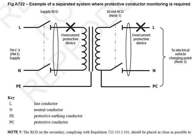
  • Just out of curiosity, does anyone know of any instances at all of option 722.413 being used for real? (i.e. use of electrical separation to supply EVSE - e.g. as per fig A722).

      - Andy.

  • Hi AJ, at present I have not seenthis in real world. However I am looking at how we could utilise this. 

  • It is permitted, its not clear that all risks are eliminated.

    Its an interesting one, and while it removes the question of PEN loss it is not without another class of risk - the 'PC' to the car is completely off earth, as drawn, not with an electrode or anything,  and can float to an arbitrary voltage relative to terra firma, so a short, or more likely a moderate impedance  contact from the secondary side L or N to true earth, via a damaged cable on the driveway, could leave the car chassis at an elevated potential. (portable gensets have the same weakness.)


    The transformer of that wattage (even just a 7kW one) is quite big, (*) and without a grounded interwinding screen betwixt the primary & secondary the interwinding capacitance could easily be 1000pF or more (30 j kilohms perhaps ), so there could well be a noticeable tingle in normal use. 

    Mike

    * its also a big heavy so and so.
    Couple of 'old hand' formulae for first estimates . 50Hz and modern "transformer" steel.

    A=()/6
    A is the core cross section in sq inches and W is the V.A - say 7000 in this instance.
    sqrt 7000 is 83 and of that is about 14 sq.in - so in metric  a central core leg of  100mm* 100mm (0.01m2) would do. 

    So how many turns. 
    V=4.44 A Bmax

    V is the winding voltage
    F is the mains frequency
    Bmax is the field in the core - assume 1 if not known
    N is the number of turns
    A is the cross section area in metres

    If N is taken as 1 it gives the turns per volt for any winding on the core
    so about 2 Volts per turn., say 2 windings of 120 turns of wire capable of 30A when close wound.

    Probably not much change from a cube of side 40cm and a weight of ~ 75kg by the time you add the windings and the enclosure.


  • via a damaged cable on the driveway, could leave the car chassis at an elevated potential. (portable gensets have the same weakness.)

    I think the 30mA RCD on the secondary (unusual for true separated systems) is meant to cover that eventuality.

    I'm not sure if the 'isolating transformer complying with BS EN 61558-2-4' would imply an interwinding screen (or equivalent means of reducing coupling between primary and secondary)? (it does seem to be a bit of a flaw in the concept of isolation if capacitance between primary and secondary means they're not entirely separated from each other).

      - Andy.

  • For full fault protection you probably want both the two pole RCD drawn and a three pole RCD encompassing L, N and PC between the two pole RCD and the transformer / N--PC link.

    It is unclear why the PC exists as it looks like an opportunity for fortuitious earthing which is the opposite of what we want here.

Reply
  • For full fault protection you probably want both the two pole RCD drawn and a three pole RCD encompassing L, N and PC between the two pole RCD and the transformer / N--PC link.

    It is unclear why the PC exists as it looks like an opportunity for fortuitious earthing which is the opposite of what we want here.

Children
  • It is unclear why the PC exists as it looks like an opportunity for fortuitious earthing which is the opposite of what we want here.

    It'll be because the EV power protocols check for the presence of an working earth connection before allowing charging to commence. Without the PC (and N-PC link) the EVSE/car would refuse to play at all.

     For full fault protection you probably want both the two pole RCD drawn and a three pole RCD encompassing L, N and PC between the two pole RCD and the transformer / N--PC link.

    In what situation would the 3-pole RCD "see" any imbalance? (given the N point isn't earthed)

       - Andy.

  • You need the PC (it connects to car metalwork) to N loop to be detected as low impedance for the car to decide it is safe to charge. (some cars struggle on TT supplies with a high electrode resistance)
    There is also a pulsed DC signal/ pilot line between car and charger that uses the PC as its return and reference voltage. 

    There are a great many things that would have been easier if the charging car could have been a class II (double insulated ) device in terms of its mains connection, much like more or less all other outdoor electrical items that are hand held and/or  easy to touch, and if the  comms between car and charger had been isolated, like ethernet or even fibre. 

    There is a general problem with isolation using traditional high power transformers, that revolves around the unavoidable inter-winding capacitance, and its why the middle of the builder's 110V is earthed to make 55-0-55 rather than fully floated.  

    There is instead a massive EMC problem with the smaller lighter switch- mode equivalents running at hundreds of KHz, using the squarest possible switching waveform to minimise the time of dissipation of being neither on nor off. 

    The filters to deal interference with this tend to need an earth connection, and around 600W to 1kW is where current SMPS designs generally stop being class II and becomes class I, but like all things  electronic the limit of the possible is a bit of a moving target.

    Mike

  • Hi,

    It'll be because the EV power protocols check for the presence of an working earth connection before allowing charging to commence. Without the PC (and N-PC link) the EVSE/car would refuse to play at all.

    Ah, of course.  I definitely think cars would be better off as class II devices and I think a transition is probably possible but I doubt there is the will.

    In what situation would the 3-pole RCD "see" any imbalance? (given the N point isn't earthed)

    An imbalance would be seen in case where there was capacitive coupling or insulation breakdown in the tranformer windings  Whether an RCD is the correct way of addressing that risk is a different question.

  • For full fault protection you probably want both the two pole RCD drawn and a three pole RCD encompassing L, N and PC between the two pole RCD and the transformer / N--PC link.

    It is unclear why the PC exists as it looks like an opportunity for fortuitious earthing which is the opposite of what we want here.

    No, definitely not a 3-pole device. 

    The PC is required to do two things:

    (a) As others have said, permit EVSE (charging points) and EVs that incorporate protective conductor monitoring to actually permit charging; and

    (b) As the EV is Class I equipment, and EVSE may be, or incorporate, Class I equipment, it is absolutely needed to permit the RCD to operate for a fault between a live conductor and an exposed-cponductive-part given (a).

    This type of system, with protective conductors connected to a live conductor, and possible Earth (but not necessarily) is used quite frequently with temporary generating sets, and is described in BS 7430:2026 as 'IN-S'.

    The RCD located immediately after the source, with the live conductor to PC referencing point on the source-side of the RCD, is absolutely vital for safety, to prevent a very nasty surprise, if the live conductor not referenced to the PC becomes accidentally Earthed (say if a cable is partially damaged).

  • No, definitely not a 3-pole device.

    The PC is required for two reasons.

    First, as others have said, it allows EVSEs and EVs with protective conductor monitoring to recognise a valid protective conductor and permit charging.

    Second, because the EV is Class I equipment, and the EVSE may also be, or incorporate, Class I equipment, the PC is needed to allow the RCD to operate for a fault between a live conductor and an exposed-conductive-part.

    This sort of arrangement, with protective conductors connected to a live conductor and possibly to Earth, but not necessarily so, is used quite often with temporary generating sets. It is described in BS 7430:2026 as “IN-S”.

    The RCD immediately after the source is absolutely vital, with the live-conductor-to-PC referencing point on the source side of that RCD. Otherwise there is a real risk of a nasty surprise if the live conductor that is not referenced to PC becomes accidentally earthed, for example through a partially damaged cable.

  • My point was not to suggest that the two pole RCB was not required but to point our that if there is sufficient coupling (capacitive or conductive fault) between the core, body or any interwinding screen of the transformer and its secondary to present a hazard then the arrangement shown does not provide protection in the context under discussion and that an additional 3 pole RCD would be required to achieve that.

    Whilst I accept that the PC is necessary for various reasons the most significant of which is allowing the two pole RCD on the secondary to be effective, there is a risk if this becomes connected to anything, including any PEs that might be present (the context of this discussion).  The PC is an unbonded conductive part so shouldn't be exposed anywhere other than at the vehicle itself and should be treated as a live conductor - e.g. the use of T+E or armoured cable for wiring on the transformer secondary side shouldn't be permitted - I don't know if this is clear?

  • I think we’re largely in agreement on the principle. My point is that the transformer secondary is intended to remain electrically separated from earth, with the PC acting as the reference conductor for the separated system rather than as a protective conductor in the conventional sense.

    If the PC were inadvertently connected to PE or any earthed conductive part outside the vehicle, then yes, the electrical separation would be compromised and the assumptions behind the arrangement would no longer apply. That’s why the integrity of the separated system is critical.

    Where I differ is on the need for an additional 3-pole RCD. If the transformer complies with the relevant product standards (including limits on leakage and insulation between primary, core/screens and secondary), and the secondary is installed as a separated system in accordance with BS 7671 and BS 7430, then the 2-pole RCD on the secondary should provide protection against a second fault. A 3-pole RCD would only become necessary if we assume a fault path that effectively defeats the electrical separation, in which case the installation is already outside its intended operating conditions.

    I do agree that the PC should never be treated as a conventional PE and should not be exported or bonded to external earths. Maintaining that separation is fundamental to the safety of the arrangement.

  • The PC is an unbonded conductive part so shouldn't be exposed anywhere other than at the vehicle itself and should be treated as a live conductor - e.g. the use of T+E or armoured cable for wiring on the transformer secondary side shouldn't be permitted - I don't know if this is clear?

    That does seem to be going beyond normal requirements for separated circuits - section 418.3 for instance only requires the bonding conductor to be insulated (rather than say insulated & sheathed as would usually be the case for live conductors) and clearly accepts multiple exposed-conductive-parts on the same system. Conventionally the sheath of SWA is considered adequate for separating different earthing systems (consider the typical arrangement for a TT'd outbuilding where the supply SWA is TN and then gapped at the intake position of the outbuilding - so the final length of the SWA is within the TT equipotential zone).

    That said the A722 approach isn't really a separated system in a conventional sense (normally the connection of exposed-conductive-parts or a protective conductor to a live conductor is prohibited) - so some differences will be inevitable. It might be clearer if BS 7671 recognised it as a different system again (IN-S).

    Also BS 7671 generally only provides safety under single-fault conditions - risks from 2nd faults (e.g. earth fault and broken c.p.c. in ADS) can often remain (although BS 7671 does require protection from some 2nd faults in some situations - e.g. for additional protection). The PC conductor becoming connected to another earthing system (or true Earth) probably wouldn't of itself be an immediate hazard - you'd normally also need another fault elsewhere (e.g. broken PEN or uncleared earth fault) - so into 2nd fault territory.

       - Andy.

  • It might be clearer if BS 7671 recognised it as a different system again (IN-S).

    IN-S is now recognised in BS 7430:2016, so that might be possible in future.