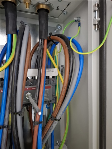
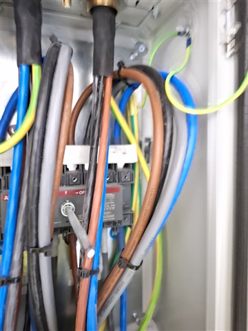
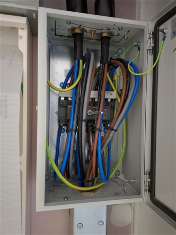
A & B supplies going through manual transfer switch to 2No DBs.
I'm concerned that this enclosure and CPCs are not bonded or installed correctly. I've also got concerns that the switch isn't wired correctly, according to the schematic.
Bonding
-
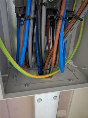
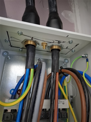
The SWAs have been glanded into the removable panels but there is no fly-lead connecting to the main enclosure. As far as I'm aware there is a rubber seal between the removable panel and the main enclosure to maintain the IP rating. I appreciate there are nuts and bolts holding this in place, but would this be sufficient as a connection?
-
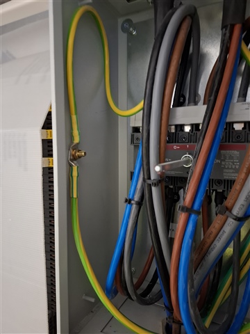
The CPCs from the supply have been bonded to the side panel of the housing, and the CPCs from the DBs have been bonded to rear panel of the housing but they have not been connected together. Although everything is connected through the housing it doesn't appear to be a robust connection.
Switch
ABB 0T100F4C
Schematic arrangement below.
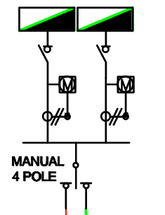
From the data sheets and diagrams available from ABB, I don't believe the switch operates how the schematic is drawn. Meaning that essentially supply A is connected to one side of outputs from the switch and supply b connected to the other side. The switch provides 3 modes of operation - All off, Side I on with Side II off, and Side II on with side I off.
I'd like to hear thoughts and opinions on this please.