New farm building and parlour

Good evening gurus!! 

We have a new installation on a farm with parlour, associated equipment and offices.

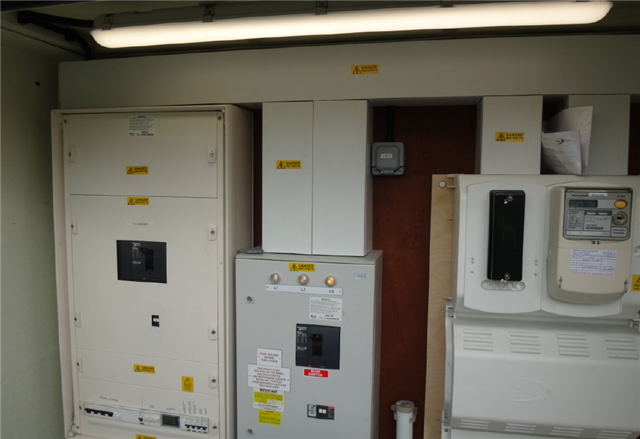
The supply is 400a three phase with PME and it is in the main plant room in the middle of building where our distribution will be located. 

With it being a farm we obviously need to have RCD protection (TD 300mA). We plan to split it over a couple of Hager Hybrid boards as we have a couple of large outgoing loads, but as they do not offer RCD TD incomer, we will be fitting two of the Hager 200a RCD enclosures and devices before the boards. 

We will need to have a panel board to feed the three boards (third is a small 12way 100a with TD for lighting and small power). My issue is separating the PME and TT as both in same room and we can not relocate the incoming supply. 

My thoughts first were to install the 6way panel board next to the incoming supply (400a tp switch fuse in place also) and leave this on PME.  Then feed the sub boards and have these on TT. I will need to separate the systems so will need to have a break in the metal trunking. Will I also need to fully enclose the incoming supply and panel board so you can not touch both PME board and TT boards at the same time? Or do I install an upfront RCD protecting everything?

it’s a tricky one as usually the supplies are away from parlours etc so can easily achieve the TT with no risk of PME in same building. 

im concerned with having a main RCD straight out the SSE supply covering the whole installation. 

  • By "parlour" I presume we're talking about a milking parlour (for cows) rather than an old-fashioned sitting room for humans,

    The traditional setup would be an up-front RCD in an insulting enclosure - so no use of PME at all. For 400A you're more likely looking at an MCCB with an earth trip (normally adjustable so you can discriminate with downstream devices). Metal clad enclosures aren't out of the question provided you can arrange double/reinforced insulation on the live conductors before the 1st RCD (leaving the sheath on single core cables is often sufficient).

       - Andy.

  • On a supply of that capacity you may prefer to have a switch and then use more than one 300mA time delay RCD in front of the installation - in effect creating more than one zone - this reduces the risks from  a 'one-out all-out'  problem.

    I must admit that while the reinforced insulation  is an approved method, I'm not personally a great fan of any metal containment for TT supplies  pre-RCD.  An insulated enclosure in a place that  is not a fire hazard  feels better. (after all insulation is what metering and DNO cut-outs do, meters have not using earthed metal boxes for many years now.)

    The other dodge where there are sub-mains out of the plant room, is to afford the SWA armour the cover of the PME earth from the origin, but to insulate it at the load end, where the TT starts. (in effect  where you use an insulating gland and the armour stops at that point - purists may over sleeve the armour at the load end,  or terminate some strands it so it is available for Zs testing of the PME part.)

    As far as earthing goes, the load side can then still be all one big TT installation, and the PME provision, in effect an exposed neutral, may be completely ignored if that is the easiest or as above just for sub-main armour.  (I can't see how your situation  here  but in a lot of agricultural settings the PME part is more or less non-existant, or just a few cables and maybe one box.)

    Note that combined electrode resistance needs to be that much lower with the higher current RCDs/ earth fault relays - a lot of the printed advice assumes 30mA instant are the only RCD. 

    Of course we can't see this installation , and  there may well be better ways  for many reasons.

    regards Mike.

  • Ok,

    Not a farm, but picture from a fuel filling station typical origin set up where we do not use the DNO earth, but install a TT earthing arrangement.

    So right hand side is the DNO cable head ( Yes, they do manufacture and install insulated ones) then the double insulated meter tails pass thru plastic trunking to again an all insulated enclosure that has the four pole main protective device with adjustable rcd as we typically have three levels of time/earth leakage current cascading. main conductors then come out of that main protective device to the section board on the left hand side of the foto and obviously now a metal enclosure earthed to the TT arrangement.

    So maybe something similar would suit your needs?

    Regards GTB