Classification of an earthing arrangement where an interconnected earth electrode system provides the earth fault return path — TN-S or TT?

Hi all. I am trying to determine if this system is considered as a TT or TNS based on the image above.

From BS7671

TN System is

A  system  having  one  or  more  points  of  the  source  of  energy  directly  earthed,  the  exposed conductive-parts of the installation being connected to that point by protective conductors.

TT System is

A  system  having  one  point  of  the  source  of  energy  directly  earthed,  the  exposed-conductive-parts of the installation being connected to earth electrodes electrically independent of the earth electrodes of the source.

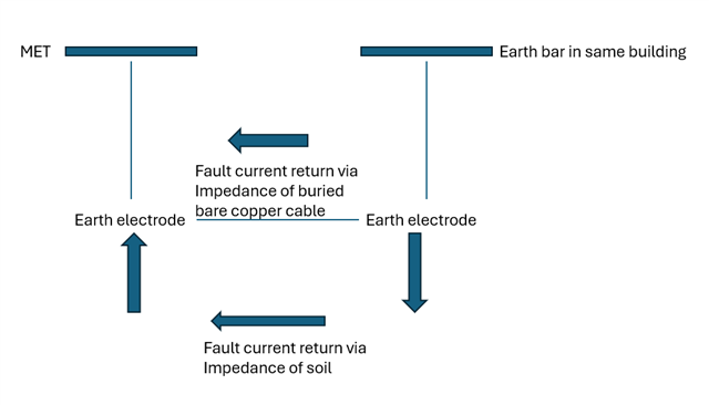
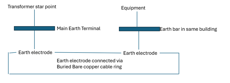
The design earth fault current return path is from the equipment earth bar to the equipment earth electrode to the buried bare copper ring back to the transformer earth electrode and back to the transformer earth bar then back to the transformer neutral.

I am trying to determine whether a fault current path that uses an earth electrode system can still be considered a protective conductor, and whether this arrangement would be classified as a TN-S system rather than a TT system, given that the installation earth electrodes are not electrically independent from the source earth electrodes.

  • Hmm, I can see why its not an easy fit into the standard tick boxes ;-) 

    But , in terms of prospective fault currents and touch voltages rising during faults, the metal connection means it is more like TN-something, so long as the earths are never separated - if they ever were it would be TT. 

    It is however more like some variant of PNB, as there is only  the one electrode, rather than one at each end. 

    Regs wise one can consider pieces of metal that are not strictly just wires to be part of a CPC  but usually this is conduit, trunking etc, not a buried structure.  

    Are there any other above ground connections linking the earth electrodes of the two buildings - such as armour on sub-mains ?


    Personally if what may happen in the future is not clear I;d recommend to size bonding and for TN fault currents and PSSC, but earth fault protect like it might one day become TT. 

    Mike.

  • Is the hidden trap, the question of who has continuous responsibility for the maintenance of the protective current pathway, and where that responsibility is handed over?

    In this case we have (I think) the DNO being responsible up to the Main Earth Terminal (as labelled), while the "Equipment" electrical system design/ownership (as labelled) is with the building's electrical contractors. However the bit between the two isn't really 'owned' and maintained by the civil side of the buried structure staff... man shrugging

  • Likely some kind of private set-up. If I was ticking a box, I would tick TN-S.  The electrode at the load end is effectively part of the earthing conductor. The electrode at the supply end is doing much as it would in a standard TN system. 

  • Where do the live conductors go? Surely, they must be accompanied by a protective earth, which would join the various earth bars/terminals?

  • Is the means of earthing distributed from the transformer via a conductor to the installation? If it is then it is a TN system.

    If the means of earthing is not distributed from the transformer by a conductor ,and the means of earthing for the installation utilises an earth electrode then it is TT. 

    JP

  • Hi Mike,

    Appreciate the detailed reply as this is the first time i encounter such a design. Didn't draw the separated neutral but this is a TN-S system. There is also no other above ground connections linking the earth electrodes of the two buildings other than the bare copper cable :( .

    I have been thinking about this for abit and have a quick follow up question.If this is considered a TN system for fault current calculations, should the earth loop impedance include the parallel return path through the earth?

  • Hi Chris,

    Thanks for the reply. From my knowledge, the live conductors to the equipment are accompanied by a protective earth. The issue i have is with the earth fault return path that slightly deviate from the conventional TN system as the earth bar is connected via the buried earth ring and earth electrode instead of the conventional bus bar to bus bar connection above ground. 

  • Hi John,

    Thanks for the reply. The means of earthing is distributed from the transformer by a conductor via the buried earth ring connected to the earth electrode. This means the earthing for the installation also utilizes an earth electrode which makes it a hybrid? Sorry, i am still having issue wrapping my head around this.

  • So, if the underground electrode failed, ,would there be a total loss of earthing, or would the CPC coming in alongside the power conductors on its own be adequate ? - if the latter there is no doubt it is TN. It just happens to have a shared  electrode as well, which in reality a lot of TNs supplies into rows of metal frame buildings sort of do by accident. 
    Mike

  • It does not seem to fit the examples given in 312.2 or . I would find it easier to understand if the live conductors were included in the diagram.

    I have been thinking about this for abit and have a quick follow up question.If this is considered a TN system for fault current calculations, should the earth loop impedance include the parallel return path through the earth?

    I think that over-complicates matters. I suspect that the multiple earth electrodes in a PME system are not taken into consideration.