One of the most common questions from electricians preparing for inspection and testing is:
"Why do we perform three different fault current tests when only one PFC value is finally recorded on the Electrical Installation Certificate?"
Although most multifunction testers can display fault current immediately, understanding why each measurement is taken is far more important than simply reading the number.
This article explains the reasoning behind each test and why comparing the results is essential for determining the correct Prospective Fault Current (PFC). The accompanying presentation illustrates each step with photographs and real test results.
What is Prospective Fault Current?
Prospective Fault Current (PFC or Ipf) is the maximum fault current that could flow at a particular point within an electrical installation.
In a single-phase installation, this value is obtained by comparing:
- Prospective Earth Fault Current (PEFC)
- Prospective Short-Circuit Current (PSCC)
The higher of these two values is recorded as the installation PFC.
This requirement is referenced in BS 7671 Appendix 14 and Regulation 643.7.3.201, which require the prospective fault current to be determined at the origin and other relevant points of the installation.
Why Perform Three Tests?
The presentation demonstrates the following sequence.
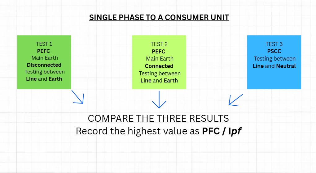
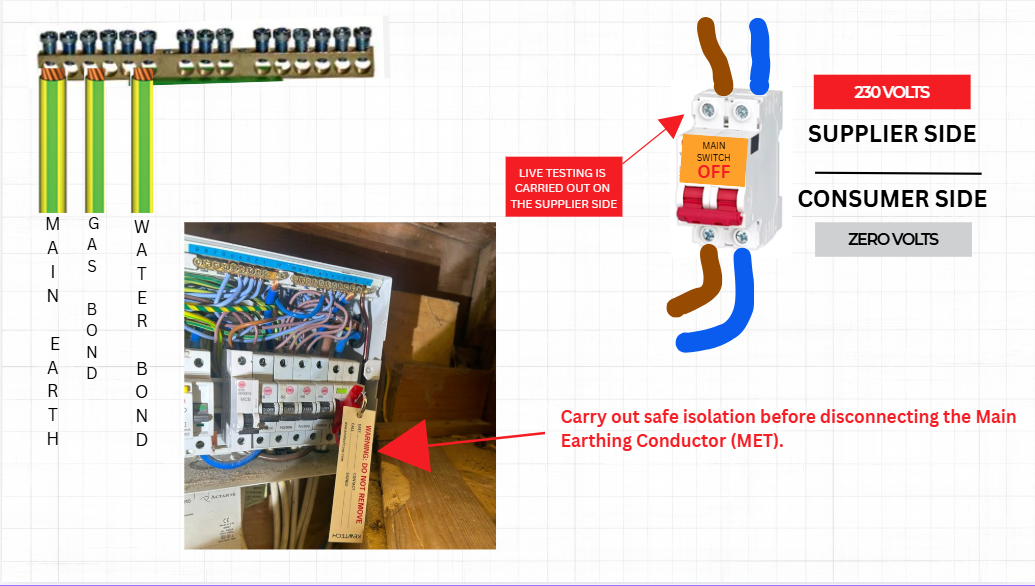
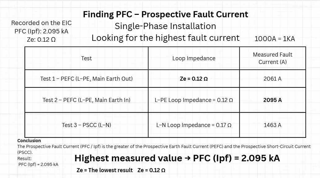
Test 1 – PEFC with the Main Earthing Conductor Disconnected
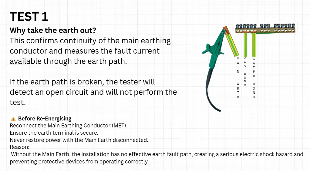
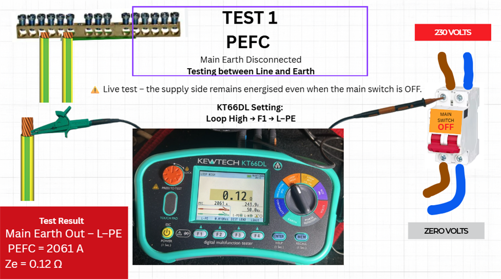
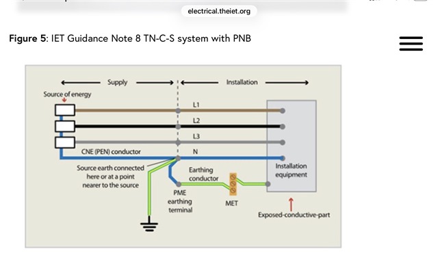
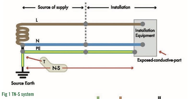
The first measurement is taken between Line and Earth after temporarily disconnecting the main earthing conductor.
This removes parallel earth paths, allowing the tester to verify the integrity of the main earthing conductor and determine the available earth fault current through the primary earth path only.
If the main earth were broken, the tester would identify an open circuit, and the test would not proceed.
Test 2 – PEFC with the Main Earthing Conductor Connected
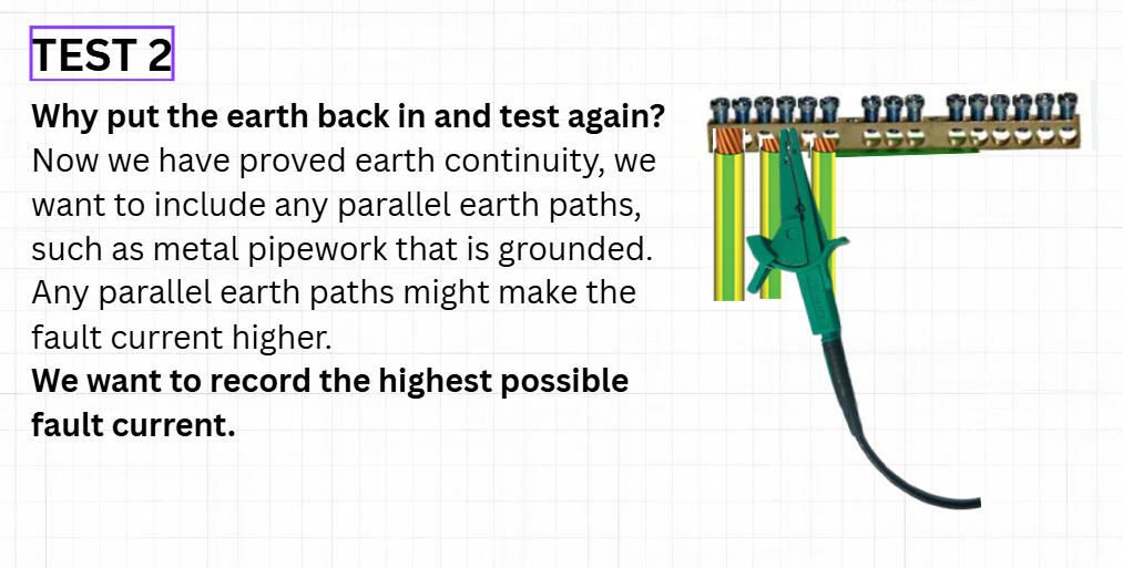
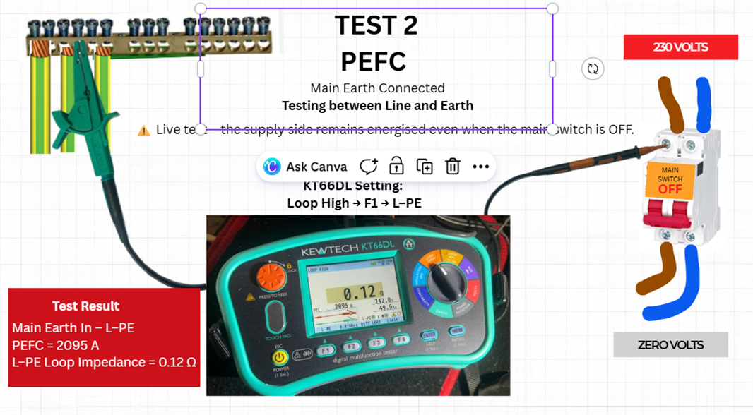
The main earthing conductor is then reconnected and the test repeated.
This measurement now includes any parallel earth paths, such as bonded metal pipework or structural steelwork, which may reduce the overall earth loop impedance and increase the available earth fault current.
This represents the earth fault conditions that exist during normal operation.
Test 3 – PSCC Between Line and Neutral
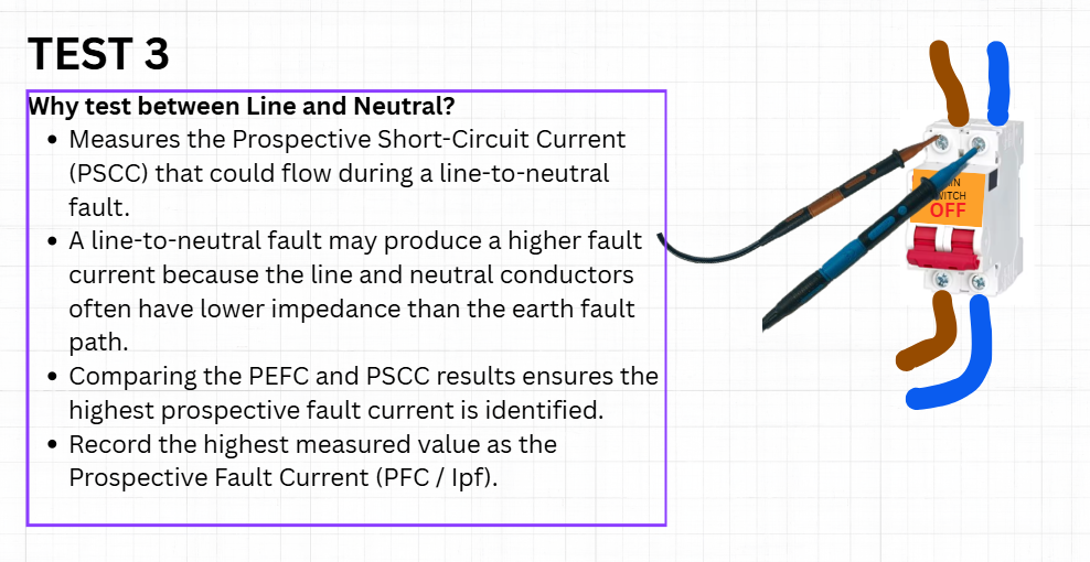
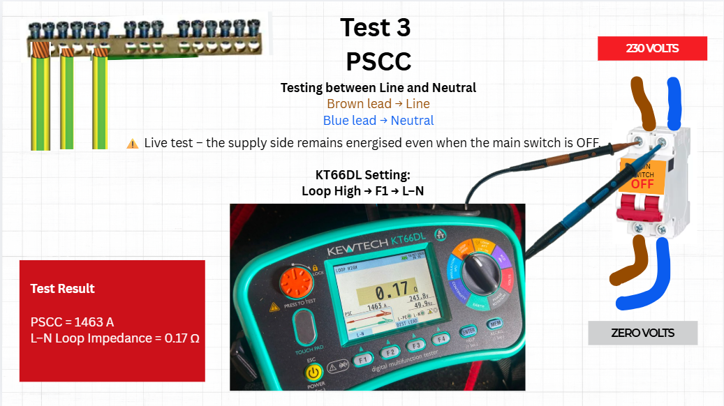
Finally, a measurement is taken between Line and Neutral.
This determines the Prospective Short-Circuit Current (PSCC).
Depending on conductor sizes and circuit impedance, the line-to-neutral fault current may be greater than the earth fault current.
For this reason, both PEFC and PSCC must be compared before selecting the final PFC value.
 ️ Practical Consideration (UK Practice)
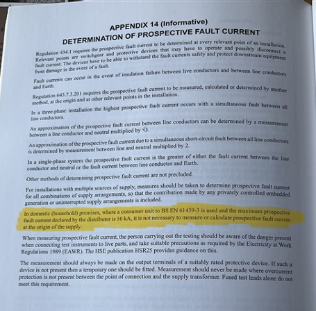
Image courtesy of Sparkingchip (IET EngX discussion).
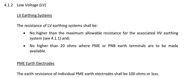
Although measuring PSCC forms part of the general method for determining the Prospective Fault Current (PFC), direct Line-to-Neutral testing at the origin is not always necessary or recommended.
For many typical 100 A domestic installations fitted with a BS EN 61439-3 consumer unit with a 16 kA conditional short-circuit rating, BS 7671 Appendix 14 and IET Guidance Note 3 recognise that the prospective fault current may be determined by enquiry, calculation, previous verified data, or other suitable methods, avoiding unnecessary live testing.
Where direct measurement is required, it should be carried out downstream of a suitably rated protective device, not directly on an unprotected supply.
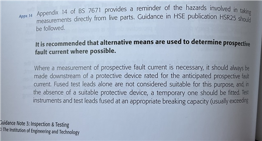
Image courtesy of Sparkingchip (IET EngX discussion).
Key Learning:
Understanding when a test is required is just as important as knowing how to perform it safely.
Recording the Correct Value
In the practical example shown in the presentation:
|
The correct value entered on the Electrical Installation Certificate is therefore: |
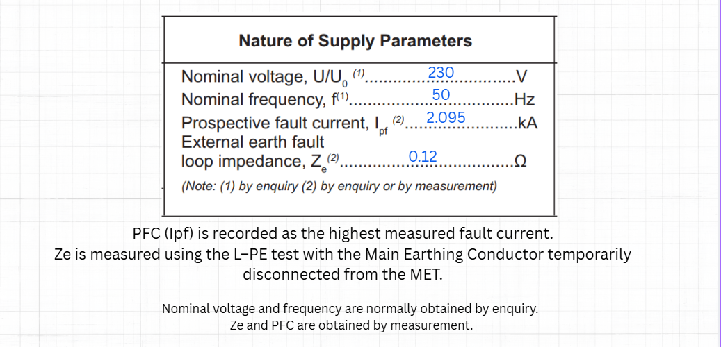
PFC (Ipf) = 2.095 kA
The Ze value is taken from the earth fault loop impedance measurement, which in this example is 0.12 Ω.
Where Are These Values Recorded on the EIC/EICR?
Safety Reminder
These are live tests.
Safe isolation procedures must be completed before disconnecting the main earthing conductor.
Before restoring the installation:
- reconnect the main earthing conductor,
- confirm the earthing terminal is secure,
- never re-energise the installation with the main earth disconnected.
The presentation highlights these precautions using practical site photographs to reinforce good inspection and testing practice.
Final Thoughts
Understanding why each test is performed is more valuable than simply memorising the testing sequence.
By understanding the purpose of PEFC, PSCC and the comparison process, electricians can confidently determine the correct Prospective Fault Current and accurately complete the Electrical Installation Certificate while complying with BS 7671.
Discussion
How do you normally explain PFC testing to apprentices or electricians who are new to Inspection & Testing? Have you found that understanding the reasoning behind the three measurements improves confidence compared with simply following the tester's instructions?
Reference:
BS 7671:2022+A2:2026 – Appendix 14 (Informative): Determination of Prospective Fault Current
Regulation 643.7.3.201
IET Guidance Note 3 – Inspection & Testing, Section 2.6.16 (Prospective Fault Current)