Need for an earth mat and connection point

From the following schematic:
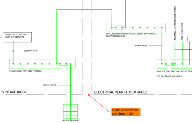
The incoming connection point is in a kiosk approximately 30m away from the main electrical switchroom. The supply is at 400V.

1 - is there a need for an earthing mat - or can the supply authorities earthing terminal be relied upon?

2 - If an earthing mat is required, should it be connected to the earth terminal in the meter point kiosk, or is better to connect to the main earth bar in the main electrical switchroom?

3 - The regulations required equipotential bonding to different extraneous metal elements. If the switchroom has no metallic elements but the main building, adjoining has a steel frame, but the steels are all concealed, is there a need to bond to the steelwork? 

Parents
  • BS 7671 does "recommend" an additional (consumer's) electrode on TN systems (411.4.2 3rd paragraph) - primarily it's intended as a mitigation against broken PEN conductors on PME systems - so a bit of engineering judgement perhaps would be needed to see if it's worthwhile, especially in similar but different situations.

    It's not quite clear from the diagram what the overall setup is - sometimes you see systems with separate HV and LV earthing systems - a mat in that sort of position would sort of match with that approach (I did note you said 400V supply, but presumably there's a HV/LV transformer somewhere...) without further evidence I wouldn't discount the possibility that the "supplier's earth" merely connects to the N star point only and the mat is needed for reference to Terra Firma (it's quite common to see the LV electrode a distance away from the transformer - to avoid importing elevated voltages into the LV system during HV earth faults). What's "normal" tends to vary by supplier around the country a bit - I'm not familiar with NIE's norms.

    In PNB systems it's common to connect the earth electrode close to the consumer's end of things rather than the source (transformer) ... but that rather depends on what needs to be earthed ... if the interconnecting cables were armoured for instance, you wouldn't want to be in the situation that during maintenance/replacement of the main switchboard, the cables could still be connected to the source but the armour left floating.

    As for steel frame, if it can't introduce a potential into the inside of the building, then I'd agree BS 7671 wouldn't require it to be bonded. That can be tricky to ensue though - you just need one pipe to be in contact with the steel behind the concealment or screw from foil backed plasterboard or a class I outside light on steel cladding supported by the steel, for a potential to be able to sneak in. There can also be other good reasons to bond even when BS 7671 doesn't require it for LV shock reasons - e.g. improving general earthing (usually good for communication/data systems and EMI in general) or to meet lightning protection requirements (a million volt flash won't be deterred much by a bit of boxing in or even a solid wall). Bonding steels that are partly buried in the ground can sometimes reduce touch voltages outside the building to some extent too (by raising the potential of the ground closer to that on external exposed-conductive-parts).

       - Andy.

  • The system is a TN-S system. The utility transformer is in a separate housing 10m away. The utility company provides cables with earthing to the meter point in our metering kiosk and incoming switch.

    From the meter point the cables supply the main switchboard which is located in the building about 20m away.

    So i am trying to determine if the earth mat is connected to the earth bar in the intake meter kiosk or whether it is connected to the earth bar in the main switchroom - or it can be either?

  • Does the transformer also have its own electrodes or  mat, or is this the first one on the LV exit side of the transformer ? i.e. is this PNB TN-S ? In the PNB case, it needs to be connected as near the origin as possible, the first kiosk, as if it is disconnected there is nothing to stop the CPC and star point of the transformer wandering up to some modest fraction of the incoming HV, decided by a capacitive voltage division whose dielectric is the interwinding insulation.

    In a sense the question to ask to see if this is earthing the transformer or the load side, is which way the current flows in the electrode in the event of an LE  load side fault. This is clearer to see in a sketch of a TT system, where the fault current sort of enters the ground from the live to the local CPS to the local electrode nearest the fault at the load end, and emerges from the ground at the transformer electrode to get back to the neutral/star point of the transformer.

    (I do appreciate its AC, and worse 3 phase so 'enter and leave' do not have their DC meaning, but I hope the intention of the short form description is clear. )

    However, in TNS it is still sensible to consider a distinction between those electrodes earthing the transformer and being the path for current to come back to the star point, and other electrodes and grounded stuff further down the line generally to be places that the fault current enters the terra-firma. (note that the phase of the voltage between the electrode metal and the not too nearby terra-firma is inverted between the two cases.)

    Regards Mike

Reply
  • Does the transformer also have its own electrodes or  mat, or is this the first one on the LV exit side of the transformer ? i.e. is this PNB TN-S ? In the PNB case, it needs to be connected as near the origin as possible, the first kiosk, as if it is disconnected there is nothing to stop the CPC and star point of the transformer wandering up to some modest fraction of the incoming HV, decided by a capacitive voltage division whose dielectric is the interwinding insulation.

    In a sense the question to ask to see if this is earthing the transformer or the load side, is which way the current flows in the electrode in the event of an LE  load side fault. This is clearer to see in a sketch of a TT system, where the fault current sort of enters the ground from the live to the local CPS to the local electrode nearest the fault at the load end, and emerges from the ground at the transformer electrode to get back to the neutral/star point of the transformer.

    (I do appreciate its AC, and worse 3 phase so 'enter and leave' do not have their DC meaning, but I hope the intention of the short form description is clear. )

    However, in TNS it is still sensible to consider a distinction between those electrodes earthing the transformer and being the path for current to come back to the star point, and other electrodes and grounded stuff further down the line generally to be places that the fault current enters the terra-firma. (note that the phase of the voltage between the electrode metal and the not too nearby terra-firma is inverted between the two cases.)

    Regards Mike

Children
No Data