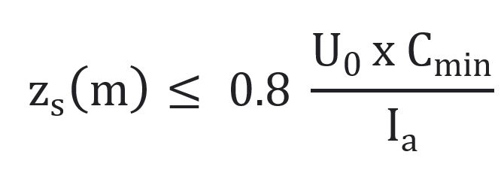
Source impedance - earth fault loop impedance for protective devices to BS EN 60898 & BS EN 60947-2

Why Upstream impedance is not included in this equation?
Say this is 230V circuit breaker,and Zs --> Impedance of the wire loop on this circuit breaker.
How about the source impedances (including the step down transformers or generator or from utility source impedances)
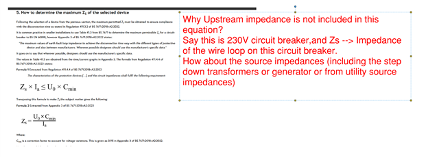
  • Well the answer of course is that all of this is included, as if affects the fault current, or at least is should be included - check the definition in the book you have lifted the formula from (I cannot get it to zoom to a resolution where I can read the image, but I can see there is one. )


    The common definition of "Zs" is the result of a live test (or a prediction of it form other knowledge) of the fault loop, at the point specified, with Zdb1 being the same thing but measured at the db no 1 or similar. Sometimes it is deduced from a measurement in another place and then adding or (dangerous) subtracting the calculated cable impedance for a known length..

    By its nature that live test includes the effect of everything in the path that constricts the fault current, all the way back to the generator, but in small installations  is normally dominated by the loop to the local substation and the final circuit itself.   

    In the same conventional notation, letters R1, R2, r1 r2 etc are normally used for the (dead tested with an ohm meter normally) resistances of the bits of wire that for just the circuit in question.

    It is always worth checking what a particular author has done, as much like insulation colour codes, the use of letters is normally standard,  except for just the odd document, where just maybe it isn't. This is especially true of foreign papers.

    Mike

  • Just took it from the link below,

    /https://electrical.theiet.org/wiring-matters/years/2023/94-march-2023/determining-the-maximum-earth-fault-loop-impedance-for-protective-devices-to-bs-en-60898-bs-en-60947-2/

  • and quoting that " 

    Zs(m) is the measured impedance of the earth fault current loop up to the most distant point of the relevant circuit from the origin of the installation (Ω).

    Confusing  as normally Zs is not taken  from the origin of the installation, i,e, the company fuse but  from the origin - full stop,  and I think that is the intention - but I see how it can be read both ways.

    I think the intention is that the measurement is a full loop Zs (including the effects of all the external components) but done at the far point of the final circuit, not as it might equally be read, measuring just that part of the impedance between the origin and the far point, (which is actually 2 tests and a subtraction.)

    If you do read it that second way, then as  you say this  ignores the impedance of the external loop, and is of course, wrong.

    Poor wording.

    Mike

  • I am not entirely sure what Nick was asking, but if you take the quotation above: "Zs(m) is the measured impedance of the earth fault current loop up to the most distant point of the relevant circuit from the origin of the installation (Ω)", I think that it would be clearer if the words, "from the origin of the installation" were omitted.

    Where else could the far point be distant from: the front door? The kitchen sink? The transformer (as the crow flies)? In our case, the far points are nearer to the transformer than the near points (as the crow flies).

    Incidentally, I am not sure that the article is strictly correct.

    The impedance of the final circuit may rise with increased ambient temperature, and indeed distribution circuits upstream of that may be affected, but the bit under the street from the transformer will not be.

  • The impedance of the final circuit may rise with increased ambient temperature, and indeed distribution circuits upstream of that may be affected, but the bit under the street from the transformer will not be.

    Or more to the point an recently energised and unloaded circuit will have a conductor temperature still at ambient (e.g. room temperature), whereas a fully loaded circuit will have its conductors warmed to a much higher temperature (e.g. 70 degrees). 0.8 equates to a temperature rise of about 50 degrees (1/0.8 = 1.00450 ish, where 1.004 is the increase in resistance factor for a 1 degree temperature rise in copper).

    Correcting for temperature on the DNO side has been a bit of a point of debate. A few years ago the regs suggested only correcting for the consumer's conductors, but more recent editions seem to suggest that the whole of Zs should be adjusted (not sure why, I suppose DNO lines may be subject to changes in loading, perhaps seasonally, or perhaps because 0.8 is a bit arbitrary (a lot of new build sites are a lot colder than 20 degrees when tested) and a bit more of a margin was wanted).

      - Andy.