The autonomous Unmanned Aerial Vehicle (UAV) drone market is growing at a fast pace, with applications including maintaining security, monitoring assets, providing an Intelligence, Surveillance and Reconnaissance (ISR) function in the defence industry [10], facilitating rapid logistics [7] [8] and providing passenger services with Urban Air Mobility (UAM) [9].
How are autonomous UAV systems designed, allowing the drone to fly without a human pilot? What components are required for an autonomous UAV system? This article gives a brief overview of the system architecture for a battery-powered electrical copter-based UAV system.
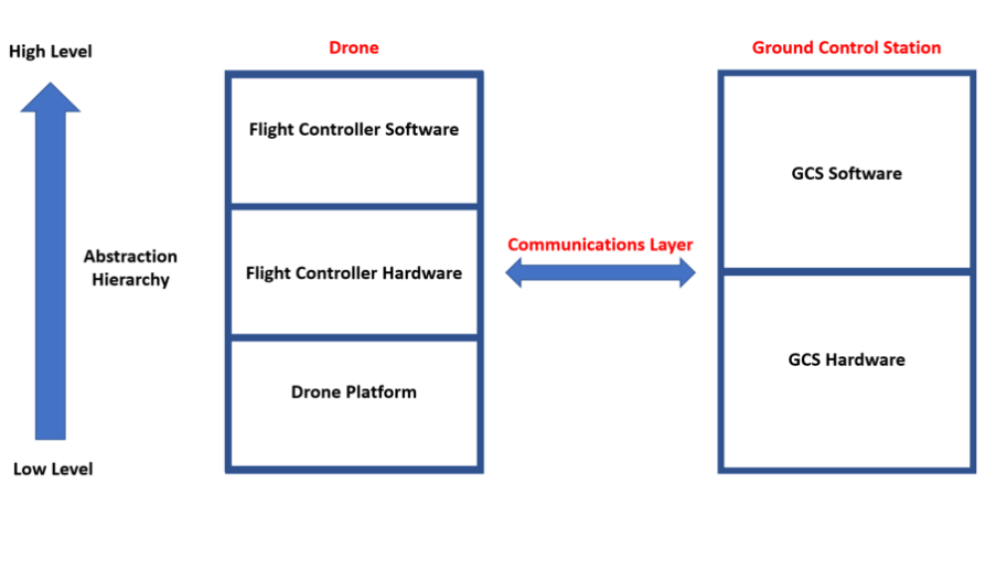
An autonomous UAV drone system often follows the Drone Flight Stack architecture as shown in Figure 1. This graphic shows three major parts: the UAV Drone, the Communications Layer, and the Ground Control Station (GCS).

Figure 1: Drone Flight Stack System Overview [3]
The Drone part is made up of three sub-parts: the Drone Platform or chassis, Flight Controller Hardware (FCH), and the Flight Controller Software (FCS).
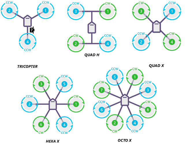
The Drone Platform covers the chassis, power and propulsion subsystem, FCH, FCS, sensors, companion computers and the on-board communications equipment. Note the key considerations for platform configuration are Size, Weight, Power and Cost, covered in the acronym SWaP-C. The frame is the chassis of a drone which maintains the structural integrity and houses all the equipment carried by the drone. Several different copter types can be used as seen in Figure 2. Note the propellers can also have several designs and will have an influence on thrust output. The power subsystem consists of a power source, for example, an electrical source such as a battery [5] (the focus of this article), solar panels [13], hydrogen fuel cell [12], petrol engine [11] or jet engine [14] or a combination of these to form a robust propulsion system. In the electrical case, a power module is used to power the FCH as shown in Figure 3. A Power Distribution Board (PDB) is used to distribute power from the power source to all the components on the drone. Electronic Speed Controllers (ESCs) are used to control the current and voltage supplied to motors which influences the speed and thrust output. Note in the power subsystem there is a three-way trade-off between the weight of a battery, the output voltage of the battery and the total output thrust produced by the electrical motors. A power budget is a good way to determine the best configuration with a typical target of a 3:1 thrust-to-weight ratio to produce a UAV that can manoeuvre without restriction. However this is highly dependent on the UAV use case.

Figure 2: Ardupilot Frame Configurations [2] [4]

Figure 3: Common Power Module photo [6]
The FCH runs the FCS and is powered via a power module [6]. The FCH is typically connected to the ESCs, GPS receivers, sensors, ground controller and telemetry communication radio modules, and companion computers for on board data processing. An example FCH is Pixhawk 4 or Emlid Navio 2.
The FCS runs on the FCH and is used to estimate and control the parameters of drone flight including roll, pitch and yaw, velocity, and height of the drone in 3D space using a controller such as a Proportional Integral Differential (PID) controller. The FCS uses data from a host of sensors including typically a magnetometer sensor to determine orientation with respect to the North Pole, an IMU sensor to determine pitch, roll and yaw axes orientation, a barometer sensor to determine altitude, a GPS receiver to determine global coordinates and speed of flight, and a downward-facing lidar or radar acting as a second source of altitude data. The FCS is designed to work in a closed-loop feedback system. It continually receives feedback from the Electronic Speed Controllers connected to the UAV motors and uses sensor data to determine errors between the actual position and desired position in an autonomous waypoint guided mission plan from the GCS. If the position is incorrect, the FCS will adjust the drone’s position whilst maintaining continuous smooth and stable flight during both manual and autonomous modes. Examples of FCS include the Ardupilot and PX4 open-source flight control software.
Drones can utilise many sensor types in addition to those found on the FCH to provide a valuable data stream of the environment around the drone, for example, lidar or radar distance measuring and cameras using visible or infrared light. A companion computer compliments the FCH by providing additional computing power on board the drone, enabling the user to program and test different flight control programs, or implement various algorithms including Artificial Intelligence (AI) applications such as using a Convolutional Neural Network with input camera video to detect and avoid objects in real-time. Example companion computers from high to low compute power include a Nvidia Jetson Nano, Raspberry Pi or an Arduino. Note a companion computer is usually connected to the FCH via a protocol such as MAVLink and runs an additional software package for autonomous control such as DroneKit. The communications equipment used to facilitate the Communications Layer is often of two telemetry module types. One to control the drone manually [15] at for example 2.4GHz radio frequency with a ground remote controller [17]. The second is typically used to relay autonomous mission guidance to the FCH from a laptop running the GCS and transfer data such as speed and heading back to the GCS to verify the mission is being followed over a 433 or 915 MHz radio frequency channel [16]. A variety of other data packets can be sent for safety commands such as Return To Home if signal connection is lost or if the power subsystem is failing.
The GCS is used to control the drone, with hardware typically consisting of a ground-based laptop to run the GCS software, a telemetry radio for real-time autonomous flight guidance and data collection from the drone, and a radio remote controller is often used to manually operate the drone as a backup. The GCS software often has a map interface to allow the user to plot waypoint guided routes and display the UAV’s current GPS position. Examples of GCS software include Mission planner, QGroundControl and BetaFlight software. The GCS also allows for the calibration of FCH components such as the magnetometer, accelerometer and IMU sensors. Furthermore, it can allow the user to simulate flight plans and test waypoint guided routes with environmental conditions such as strong wind, without risking the loss of the drone.
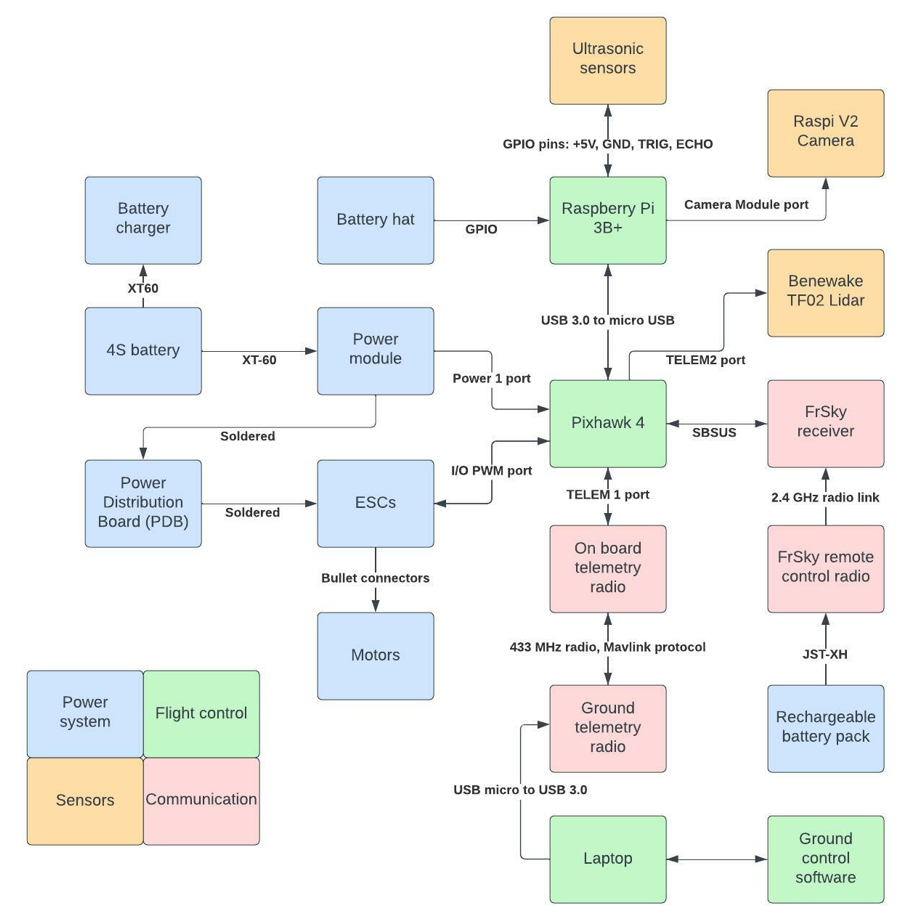
Finally, Figure 4 brings together the contents of this article into an example high-level UAV system architecture diagram.

Figure 4: Example High-Level Drone System Architecture Diagram
I hope this article provoked some thoughts on autonomous UAV systems and will begin to develop a community on UAV systems, whether autonomous or manually controlled, within the IET.
References
|
Reference Number |
Document Title |
Document Reference |
|
[1] |
ESC Firmware Protocols |
|
|
[2] |
Ardupilot Coper Frame Type Configuration |
https://ardupilot.org/copter/docs/frame-type-configuration.html |
|
[3] |
High Level Perspective of a Flight Stack | Drone Programming |
|
|
[4] |
Connect ESCs and Motors - Ardupilot |
https://ardupilot.org/copter/docs/connect-escs-and-motors.html |
|
[5] |
Lipo C Rating Explained – What does the number mean? |
|
|
[6] |
Common Power Module |
https://ardupilot.org/copter/docs/common-3dr-power-module.html |
|
[7] |
Droneamics |
|
|
[8] |
Skyfarer |
https://www.skyfarer.co.uk/blog-posts/medical-delivery-trial-update |
|
[9] |
UAM consortium project |
https://www.nats.aero/about-us/research/n/uk-urban-air-mobility-consortium-project/ |
|
[10] |
Watchkeeper UAV |
|
|
[11] |
Flylogix |
https://flylogix.co.uk/project/methane-emissions-monitoring/ |
|
[12] |
Hydrogen fuel cell drones |
https://www.unmannedsystemstechnology.com/company/intelligent-energy/ |
|
[13] |
Phasa-35 solar UAV |
|
|
[14] |
Hydra drone |
|
|
[15] |
Example 2.4GHz transceiver |
https://www.flyingtech.co.uk/product/flysky-fs-ia6b-6ch-2-4ghz-afhds-receiver-rx-with-ppm-telemetry/ |
|
[16] |
Example 433 MHz transceiver |
|
|
[17] |
Example ground remote controller |
-

Arkadiusz Wieclewski
-
Cancel
-
Vote Up
0
Vote Down
-
-
Sign in to reply
-
More
-
Cancel
Comment-

Arkadiusz Wieclewski
-
Cancel
-
Vote Up
0
Vote Down
-
-
Sign in to reply
-
More
-
Cancel
Children