This discussion has been locked.
You can no longer post new replies to this discussion. If you have a question you can start a new discussion

Control (Dimming) Options for 12V LEDs on Motorcycle?

As well as an Engineer (admittedly retd), I'm also a motorcyclist. Just decided to try and fit my M/C with some additional lamps so that it shows up better amongst the pretty Christmas trees that are nowadays marketed as four wheeled individual transport. You've probably seen a similar effect on the big chunky crossing-continents style bikes.

(This paragraph is a background rant, skippable) I wanted to achieve something akin to a daylight running light (DRL). However, on looking at what I can buy, there's a problem. It seems aftermarket lamps for motorcycles are generally sold as fog/spot/driving/auxiliary lamps. I mean, the sales blurb claims one lamp is all of those (and more). Which is odd, as the beam pattern (and homologation, where done), of fog and spot lamps is completely different. And indeed regulations limit the use of fog lamps to, err, fog, and I believe the use of spot to with main beam (Although I have also heard that these regs don't actually or entirely apply to M/C - I'm uneasy about that, especially abroad). I think “driving” means same as “spot”, and “auxiliary” means, well, nothing much. In summary, the cheap suppliers were selling snake oil, and the expensive suppliers sold homologated lamps for use in fog or with main beam. Spot type lamps are also especially useless to me, as my bike's LED dipped beam is quite visible over a narrow angle, but very weakly visible off centre, I want a wide spread.

So, I bought two general purpose 10W each, 12V packaged vehicle LEDs, sold as much for off roaders or lighting load areas. A garage test shows a nice wide, unfocussed, spread. I think they will be very visible in the day, over a wide angle, and at night on dark roads (with main beam), will help illuminate around bends.

But, I'm concerned that at night in busier areas, they may be too bright and dazzle other drivers, or cause unwanted aggravation. So, I'm wondering about a dimming arrangement, so I can manually dim them, and, hopefully, override that with the high beam.

I am not assuming they'd behave in a simple linear(ish) fashion like an incandescent bulb, but have nothing else to work on. They might even be smart enough to maintain full output at much lower supply voltage. They might really dislike being fed PWM. I don't want to try to dismantle them to find out (cheapskate only bought 2), as they will really need their weatherproofing. Anyone know what circuitry might be typical in such products?

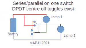
Thought A was to switch them between normal parallel connection and series, with a switch and mainbeam driving a DPDT relay through diode OR logic. However, it gives no real design choice of how dim - probably too dim, 6V may not be enough to operate (or reliably). And it seems the automotive industry doesn't offer DPDT relays in “outdoor” packaging with spade terminals (only SPDT).

Thought B was to put in a series resistor, shorted by a SPST relay, switched as above. But the resistor would have to be pretty chunky, and get hot, so presents a bit of a packaging problem on a modern M/C, with every crevice rammed with pipes, wires & boxes.

Any guidance or tips'n'tricks on these sort of packaged LED products appreciated?

  • Well, these lamps are certainly more use than the other set of “China's finest” which arrived and I tried yesterday. Those were advertised as 3 mode, but unfortunately they mean that (i guess) they used a bicycle lamp controller. So when turned on, it's nice & bright. Next time it's turned on, it's dim. And the next time, it flashes. Three modes in a cycle. I can't see any use for it on any kind of motorcycle. And at 12V, nor a bicycle either. Maybe an e-bike?

    Yesterday in my quiet close, I observed that the (original) lamp is roughly the same brightness as Honda's dipped beam (also LED), although very different pattern. So tonight I'll ride out and see if it gets me flashed or hooted.

    I'm hoping the OP and resulting replies can remain an interesting, but acedemic, exercise. 

    For future reference, these nominally 10W LED lamps are actually 5W. Some, including I think some homolugated ones, are advertised as 60W. If they really are (they don't mean halogen equivalent), there's going to be a strong case for dimming those, severely, for e.g. urban use. 

  • If each light does have a switch mode power supply, it will be actively trying to prevent any dimming.  If you drop the supply voltage, it will increase the current so that the wattage remains the same.  If you chop the supply with a PWM regulator, it will draw more current when the power is on, storing it in a capacitor.

  • Thanks Andy. I just tried out a similar PWM module I bought originally for 12V fans. It's from MFA/Como Drills, rated at max 3A continuous (much less than yours!).

    Min 0.3A (one lamp) 0.48A (two in parallel)

    Max 0.38A (one) 0.79A (two, cf 0.64A connected directly).

    I suspect that these current measurements are a bit meaningless, a product of the digital multimeter sampling (perhaps I should use the analog meter for current). At least I hope so, as otherwise it's somehow leaking 150mA at max (with no lamps connected, quiescent current was 10mA).

    The unit did seem to stay cool compared to 15R, which is what one would hope for PWM.

    However, it didn't achieve much dimming (at its dimmest it was a lot brighter than with 15R), and reached its max long before it ran out of knob travel.

    I guess that - as some previous replies - the units work down to quite low voltages, largely as a result of the LED's characteristics, which means the voltage range over which useful dimming occurs is quite small, therefore a bit hard to control, especially thinking about temperature stability etc. PWM should in theory offer a wider range. Clearly I should add a scope to my shopping list, to see what PWM that unit is doing!

    I think my next task is to compare the lamp brightness to my bike's dipped beam. Really, that should have been my starting point. If it's not brighter, to an offensive extent, perhaps I can duck the dimming altogether. If so, apologies for wasting everyone's time. Let's see.

  • What I would do is just use one of these 12v LED dimmer switches (many other suppliers of these are available, CPC just happened to come up first):

    https://cpc.farnell.com/tiger-power-supplies/tgr-dial-dim/led-driver-dimmer-switch-12vdc/dp/PW04905?mckv=s7dEAeR9X_dc|pcrid|224680288544|kword||match||plid||slid||product|PW04905|pgrid|48556615353|ptaid|pla-833287725340|&CMP=KNC-GUK-CPC-SHOPPING&s_kwcid=AL!5616!3!224680288544!!!network}!833287725340!&gclid=Cj0KCQiAhMOMBhDhARIsAPVml-FpJMBbUHa_Nre-1KhheqEDdtln0zltz86thXhKrYeZ3Ak4fxoJUnkaAi-9EALw_wcB

    Ok, might need a bit of repackaging for a bike, but they do work very well, I've used them for a couple of projects now.

    Have fun!

    Andy

  • Cheers. 

    I spent quite a while last night contemplating the physical form, how to fit it in, and where to mount the switch. That's a much harder problem, for me at any rate, than the electrical performance.

    I probably have a DPDT toggle around, but not a waterproof one. Nor readily mounted on handlebar. The other problem with using a switch, rather than a relay, is I can't hook it to the dipswitch. I really don't want to be searching for a second dipswitch whilst being dazzled on a dark road…

    I ended up wondering if I should buy a PCB mount DPDT relay and screw terminal and a waterproof project box. But screw terminals aren't great on a M/C… Yet the thing needs some service access/removal means. 

  • minimum efforts

    ae8900077615a8a557146842e105d7bc-huge-series_par.png
    A simple no sweat solution
  • Besides thanking Mike for that very helpful detail, I must correct my previous observation that my 15 5W doesn't get hot. I did an hour's soak test, it got very uncomfortable to touch, though didn't burn my skin. I suspect in itself that's no harm, and I can add a heatsink, however it probably is not ideal around the motorcycle, so if I go that way, I need a bigger one.

    I'm reluctant to open up as I'm short of time before a upcoming trip, and my electronics skills are, ahem, not going to quickly produce a reliable solution. I think the heat aspect prohibits the simple insertion of an, err, 30R in each lamp. It would be neat, though, to replace the absurdly short 2 wire cable with a 3 wire one for full/dim. 

    I'm also reluctant to try a reversed polarity test - these are cheapies after all!

  • your test results imply something like 5- 6V worth of LEDs with resistor in series- are they polarity sensitive?  - if not there will be a diode bridge in there or a second anti-parallel string of LEDs.

    BUT the ebay advert suggests 10-30V operation so maybe there is a switcher in there, which will confuse matters enormously.

    The I/V curve will tell you that.

    Realise that design wise there will be nothing in there that does not have to be. - this is market forces.

    The bare LEDs will have an exponential turn on with a knee voltage of perhaps 2V per chip, and a doubling of current every 20mV or so thereafter - hence the series resistor in the simple design. In your shoes I'd probably be gently undoing the allen screws at the back and photographing the insides to see what room there is to make a mod.

    Mike.

  • Former Community Member
    0 Former Community Member

    Gideon: 
     

    Blimey, that's plumbing!

    But I did better than expected. Firstly I wired one up with my old car battery (steady @ 12V), measured current … revealing that an eBay item titled “2x Bright LED Car Bike Motorcycle Work Driving Fog Light Spot Beam Lamp 10W” is only 10W if you sum both lamps. 0.32A = 3.84W @ 12V, I'm prepared to believe 5W @ alternator voltage. Humph. Anyway, still seem quite bright.

    Then I wired both up, in series. They came on, but much dimmer. 0.09A so 0.54W. Even this case was very visible at night from about 25 metres away.


    If they are dimmer when in series, i.e. 6v across each, why not put 2 on the bike wired to be in parallel on “main” and in series when on “dip” that would be easy with a relay or two.


  • Blimey, that's plumbing!

    But I did better than expected. Firstly I wired one up with my old car battery (steady @ 12V), measured current … revealing that an eBay item titled “2x Bright LED Car Bike Motorcycle Work Driving Fog Light Spot Beam Lamp 10W” is only 10W if you sum both lamps. 0.32A = 3.84W @ 12V, I'm prepared to believe 5W @ alternator voltage. Humph. Anyway, still seem quite bright.

    Then I wired both up, in series. They came on, but much dimmer. 0.09A so 0.54W. Even this case was very visible at night from about 25 metres away.

    Of course, I don't know the relation between brightness and watts. I tried using a (top notch) bicycle lamp as a reference but it had a tighter beam, brighter in the centre, so hard to compare. Perhaps I should adjust the distance until it looks the same.

    A determined rummage in my bits box found 15R and 24R power resistors. Wired them each in (with both lamps in parallel):

    96599adb23bdce4cfdc15d5950044d29-huge-screenshot-2021-11-10-224427.png

    Horizontal scale being my added series resistance. The 66.6ohm case is actually the 2-in-series case, the resistance is the deduced resistance of the other lamp - which could be wildly out if there was out-of-phase badly smoothed PWM going on in the two lamps, I suppose.

    The plot looks very sensible, however, plotting the voltage at the lamp against the lamp wattage is very odd looking, possibly the lamp is functional from 6V upwards, and taking as much current as it can, limited by the resistor. A bench PSU would indeed be invaluable to work out what shape that curve is (or, I guess, some much lower resistances 8ohm, 5ohm, 3ohm).

    7791fadbab9b3bbea16b8cff44456843-huge-screenshot-2021-11-10-230251.png

    I used a resistor shorting switch so could compare brightness, but TBH it's so subjective I can only really say it works and is dimmer.

    So I think now I have three usable pathways:

    • As they're only 5W not 10W, just bung them in.
    • Wire in with 15R in series to the lamps in parallel, with a relay to short the R, and diode logic so a switch OR high beam shorts out the R. That means “dip” is about ¼ power.
    • As above but buy some other R.


    Conveniently, my 15R is rated 5W, about twice what it will be handling. Of course, I don't know what temperature it would get to @5W. I don't want it getting too hot, and at a standstill, close to the engine, it may be a bit taxed. I'd better make it a metal bracket as a heatsink to help it out.

    Any other suggestions welcome. Especially if they don't involve plumbing.