This is not a question really more of a blank thread to prevent my waffling about the Essex Scout Jamboree cluttering up another thread.
For those who don't know I've just spent a couple of weeks being far more hands-on than is normal for me these days with the electrics of the Essex Jamboree- think 10000 Scouts and leaders in a field, lots of gensets lots of wire and a rather hassled team of us keeping the lights on and diesel flowing. But I also like to take the chance to chat and see what folk are doing who work in other areas.
Should I have had a third pint before waving my arms around like Kermit the frog over our only set of sketches that were at that point the current best plan for the next day, well with hind-sight, probably not. Still they dried out OK, and were just a bit sticky next day and I got the coveted 'lemon of the day' award....
![]()
As someone asked my role, it is not assigned in a formal way -we all volunteer, so it is better seen as a controlled anarchy where we do as much as we are happy with !
My role, in advance, was some sums about forces on overhead cables, to prove to the H& S team we had safe festoon lengths and wind resistance, and then creating voltage drop tables. In terms of design, not much more than load and lengths and that had largely been pre-done by someone else, then the actual build is more like running around with pre-wired leads and fittings so closer to BS7909 really. Hierarchical RCDs and earth fault relays, 34 gensets including two synchronous pairs, one for catering at 400kVA total and one for stage at about 300kVA. My special skills apart from running round with arms full of cable and radioing through for adapters, were earth rod testing and odd EMC matters. Once built to keep it running is all about fuel, either checking tanks or changing filters. Or, just occasionally the odd worrying leak,
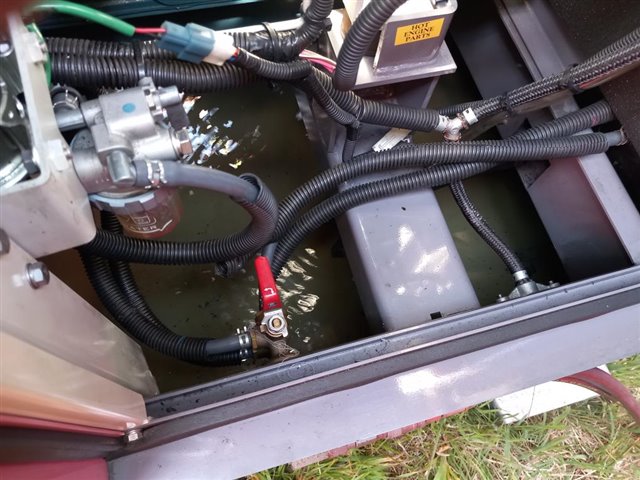
Yes, those wave patterns really are in several inches of diesel oil filling the bund of a 40kVA unit, A leaking fuel line has been filling it slowly overnight, and we are almost drowning the battery and the fuel valves.
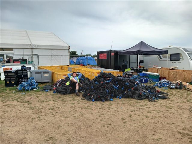
and at the end, when all the mains cable has to be coiled up again, there is quite a lot of it. the human, (me) is for scale.
Mike.
PS those tandem gensets and the fuel tank for the week,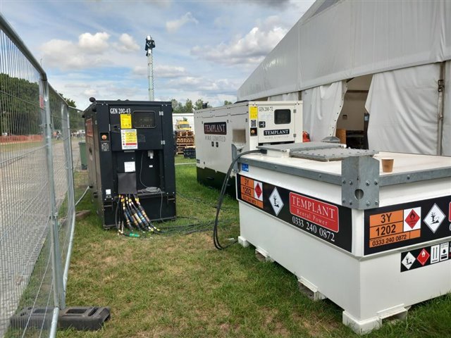
I'm getting past it, I'm feeling tired after just running and plugging in a few extension leads. The good news is no need to worry about 30mA RCDs at this size... This box feeds 6 sets of 128A and supplies lower level distro for staff catering and are pretty much fully loaded in the hour or so before meal times. It also needs 3 or 4 people to position it....
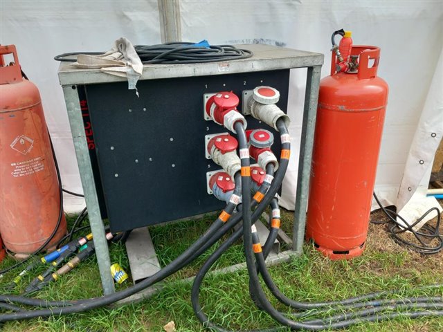
Be re-assured that rest of the cylinders were in a cage somewhere further from the tents. At the kitchen, some co-siting is unavoidable.
Actually gas and fire risk management is a serious concern, and the camping groups have to be sited and laid out so that their kitchen areas are not adjacent and are still far enough from their own and each other's sleeping areas. Spare bottles are to be stored away from that area. This leads to a lot of widely spaced cylinders exposed alongside unusually wide walkways, which looks a bit odd but is not as silly as it at first appears. You certainly don't want cylinders in tents or cookers under canvas that is going to be closed.
Some regulations have odd effects. Declaring one large tent to be a 'cinema' suddenly requires it to have 3 hr battery backed up emergency lighting over its exits. despite the fact that the occupants will all have torches and a good fraction are probably wearing pocket knives that in an emergency would allow them to walk out through any tent 'wall' in seconds even if its not the proper exit... A situation not seen in any normal cinema.
Mike
Looks fun ! Noticed the use of Veam connectors. We are utilising them on our sites as temporary generator connection points. In the event of a supply or generator failure, they facilitate quick connections for the hire set. Additionally, they are employed for load banking at the generator, eliminating the need for permits. So
earth rods were installed for the hire sets? If so, what readings were obtained? I have a keen interest in temporary power systems, James Eade’s books are highly informative on the subject.
we were generally striking in 1m long 9mm dia copper plated steel rods and seeing resistances as low as 14 ohms in the damper bits of the field, but more typically 20-40 ohms, Higher up the slope where the ground had been more baked the highest we saw was 70 or maybe 80 something from memory. Essex clay is especially conductive - I was not surprised this time, having seen it before but had the same rods been used here (Hants, Glacial outwash and in this place quiet stony/gravelly) I'd expect well over 100 ohms at best maybe over 200 for a single rod..
We did a few comedy tests as well - so 300 ohms for my 'wrecker bar' screw driver, about 150 for a genset on its skids with no rod, - but that varies a lot with the paint job. The stage also managed about 150 on damp wooden blocks on a dewy morning before we spiked it, and we did not bother to spike the climbing tower as it manages well below an ohm all on its own and we can't get far enough away to get a reliable limiting reading.. Not surprising as it is essentially supported by a nest of scaff poles driven in at least half a meter.
We spiked every generator except a couple of lighting towers that were not supplying any external load. It is all TN-S by design. Given the amount of class 1 kit involved, and the areas involved, and the earth (==grass) floor nature of the installation, I'd not really consider not earthing as a sensible option - well after the initial getting power to the electricians area had been solved. That may well have run un-spiked for a bit
M.
yes the powerlocks singles are pretty solid and the easiest way to parallel up the sets, though you need a socket set to install tails initially to the bus. This is not that set of tails, but a 63 amp one for illustration only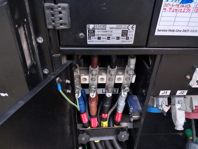
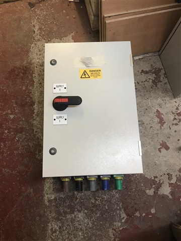
We have this equipment in place. However, when the hired 500 or 1000 kVA generator arrives, it remains on the trailer. The 240mm tails are extended and connected. The substation’s LV room is equipped with earth rods connected to the MET, but no additional earth rod is installed. What are your thoughts on this practice?
well you are then doing what we are more or less - providing a local earth (terra firma) reference for the earth (CPC of the installation. )
What you should not do -in a power cut anyway - is rely solely on the suppliers earth as you don't know what has come disconnected to cause the power cut, but as your LV room has local electrodes so that is not an issue, I suppose one should ask where the NE bond is, but I presume at the genset, so the singles cannot be earth leakage protected unless the NE bond at the mains incomer is disconnected.
Do you ever synchronously parallel run the genset with mains, or is it always a hard switch-over ? The box does not appear to be wired in, so I assume that was a pre-install photo!!
Mike.
So, In the event of a mains failure, the backup generator is activated via an automatic changeover switch. Should this generator also fail, the hired generator becomes necessary, and the generator Veam connection unit is switched to position 2 to facilitate the connection and operation of the hired set. The neutral-earth (N-E) bond at the mains incomer remains connected. All isolators are three-pole, with the neutral-earth bond located in the LV panel board (PNB) and the transformer situated in the adjacent room.
The genset operates with a hard switch-over, rather than in synchronous parallel mode. Additionally, this is a pre-installation pic. The earth rods within the LV switch rooms are tested annually using the clamp meter method. The hired set remains on the trailer but is equipped with an earth rod, which may not achieve a very low reading. Would it be advisable to install an earth pit/nest for the hired set to connect to as well?
The neutral-earth (N-E) bond at the mains incomer remains connected. All isolators are three-pole, with the neutral-earth bond located in the LV panel board (PNB) and the transformer situated in the adjacent room.
Is that like Fig 44.10 in BS 7671 then? OK, not quite as you have the lines switched, but in terms of permanently connected N and PE links? Or is the auto change-over switch 4-pole?
- Andy.
Hi Andy. The ASCO changeover is a four-pole switch. According to note 44.10, switching the neutral helps prevent electromagnetic fields caused by stray currents. Have you ever observed the effects of such an occurrence in an installation where the neutral-to-earth links from both sources remain connected?
We're about to take you to the IET registration website. Don't worry though, you'll be sent straight back to the community after completing the registration.
Continue to the IET registration site