Permanent Magnet Generator - Apparent Magnetic Flux Reduction after Rewind

Hello, I am hoping someone will be able to help with an issue that I am having with a Permanent Magnet Generator.


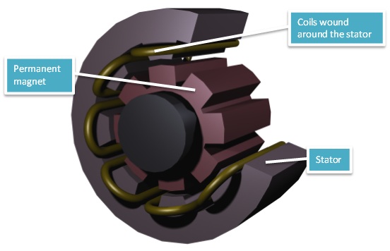
As a bit of background, the generator is connected to a turbine and thus converts mechanical torque on the shaft into electrical power. With it being synchronous the Voltage is proportional to the speed. A Variable Speed Drive is used to vary the speed to maximise the output from the turbine. The generator has 12 poles.


During initial installation, the generator was found to have been supplied to the incorrect specification. It was supplied with the wrong number of poles and wound for 400V/60Hz; it therefore produced excessive voltage for a given speed. The generator was removed from service and rewound to an unconventional 400V/95Hz. The rotor and the stator designs were unchanged. The number of turns has been reduced by 37%. I don’t have any data on the wire gauge.


Since the being rewound to the new design, the generator is producing less voltage than expected. The new windings should deliver 42V/ 100rpm, but it is fact delivering only 35V/100rpm. This is resulting in a shortfall of power. The generator has been rewound again, to the new design, with the same result. The new windings have resulted in a lower power output than was achieved with the initial windings.


Only the winding design has been changed. There is no reason to suspect a reduction in torque from the turbine or damage from bearings etc. The operation and control from the VSD have been extensively looked at and deemed not to be the issue.


My suspicion is a reduction in the magnetic flux, either from excessive leakage or possible damage to the magnets, but I am far from an expert. While reverting to the old design seems an obvious solution, I am keen to understand the exact nature of the problem.


I am reaching out to see if anyone can share some suggestions as to any possible causes of this issue.

Parents
  • Are these unloaded voltages, or if not on how much load, and how fast are you actually spinning the thing? I'd only expect a 'near' linear rise of voltage with frequency, as depending on core lamination thickness and other frequency dependant losses, there will be additional HF roll-off and 60-95 is quite a jump to assume 'all else being equal' .
    Are you seeing significant idling loss - hot cores and or higher than predicted  off-load torque?
    Lost volts alone may not be lost power- depends on the available VA, it may be easier to transform up or down to meet your need.
    Once the winding space is full, and if it isn't then either more iron or more copper would improve it, the power available is largely set by a matter of dissipation and mechanical strength.

    If you are short on magnetism, that is probably best verified  first. What form factor and chemistry are the magnets ?


    Mike.

  • HI Mike, thanks for your response, I will do my best to answer what I can.

    The nominal turbine speed is 750rpm (75Hz). So with our winding at 400V/60Hz the generator would produce 500V. This of course exceeds our limit so this was field weakened by our VSD, hence the re-design. Whilst we could achieve 750rpm this resulted in a power shortfall. 

    With our winding at 400V/95Hz the Voltage should be 315V at 750rpm. We are in fact generating only 262V. The Voltage is linear with speed and the Voltage Frequency ratio is constant at 35V/100rpm.

    For the initial windings we have measurements of the power produced just at the point of field weakening (around 600rpm 60Hz). This is not the optimum point for the turbine. With the new winding design and at the same operating point, 600rpm, the loss in power is exactly the same as the missing Voltage ca. 84%. So the lost Voltage seem to correlate exactly with the lost power we are seeing on the meter. 

    The magnets are neodymium.

    The number of turns has reduced from 22 to 14. It feels to me that perhaps the slots are not as full of copper as they were previously and perhaps this is causing some inefficiency? 

  • I may be visualizing the wrong sort of generator -  are you are spinning a disk of 6 magnets and have 12 stator coils, or a cylinder of magnets more like a car alternator, and the coils are long in the direction of the axle ? So the votlage is proportional to the  length ?

    I'm also not sure of the scale here - losses in a machine generating low powers are not likely to be easily discernible, being comparable to bearing losses etc, while even a few % at the tens of kW level are likely to be easy to find.

    I'm intrigued by the field weakening comment - I'm more familiar with that as a technique to drop the torque of motors to keep the voltages sensible at higher revs, how are you doing this?

    Mike

  • The image you have provided matches my arrangement. For scale this is a 30kW generator.

    I have 12 magnets mounted on the shaft. In the stator I have 18 coils (6 per phase). My initial winding had a total of 132 turns per phase (22 per coil). This has been reduced to 84 turns per phase (14 per coil). 

    It is my understanding that the emf is given by:

     emf = 2π/√2  x N  x  K  x  f  x  Φ

    where: N = number of turns in the winding, K is a winding constant between 0 - 1, f = frequency, Φ = Magnetic Flux

    All things being equal, reducing the number of turns should increase the frequency for a given Voltage.

    In my case, with 132 turns per phase, f = 60Hz, K=1, emf = 230V, Φ = 0.065Wb. 

    Now 84 turns per phase, f = 95Hz, K=1, emf = 230V, Φ = 0.065Wb. 

    So if the magnetic flux and the winding constant remain constant, the new design should have worked as intended.  

    However at 95Hz I only produce 332V L-L or 192V L-N. So using the above equation my Magnetic Flux must be lower or the Winding Constant <1.

    (I hope you follow)

    I am struggling to understand how or why either the Magnetic Flux or the winding constant may have reduced. A reduction in magnetic flux could be a result of demagnetisation, but I am not sure how this may have occurred. The winding constant is something I am not overly familiar with, and I wonder whether reducing the number of turns by such as large number has had an impact. Afterall, the geometry of the slots was designed for many more turns that I have now.  

    With regards to the field weakening, your comment is spot on. The turbine likes to run at 750rpm to achieve peak efficiency. With our 400V/60Hz winding, operating at 750rpm (75Hz) the Voltage would be greater than the 400V limit. So the VSD reduces the torque, allowing it to operate at 750rpm and 400V but with a lower power output - which for a generator is no good. I am sure there are people on the forum much more qualified than me to explain field weakening, but my understanding is that the VSD supplies additional current, such that its magnetic field cancels the magnetic field from the magnets and reduces the overall flux.  

  • Long ago I worked with some machines fitted with DC PM servomotors (a few kW in size). We used to send them to the local motor rewinder for repairs but found the perfomance  was reducing. We then sent them to a servo specialist who informed us that if you didn't use the correct keeper when dismantling you would loose magnet stregth. They were able to remagnetise them for us.

  • Hello Robert:

    The last time I ever got my hands on a big electric motor was when I taking a course in electrical engineering over 70 years ago. It was a motor-generator set and we had to synch up it's 3 phase output to the mains supply, using electric filament lamps.

    Bottom line is I am no expert in this area.

    However recently there was an excellent technical article published by the IEEE concerning development of electric motor windings from 1865 to 2025 which maybe some help to you.

    For example the use of bar-wound machines instead of wire wound machines.

    The article was published in the Proceeding of the IEEE December 2024 (Vol 112 No 12) pages 1831- 1849 Titled  "Hairpin Windings : Twists and Bends of a Technological Breakthrough by Stefan M Goetz  Department of Engineering, University of Cambridge, CB3 OFA Cambridge UK.

    Peter Brooks

    Palm Bay

  • Hmm. I can't see an obvious 'gotcha' with your logic -

    95/60 is of course 1.583 and your turns ratio of 22/14 is more like 1.571 so we might expect if anything an increase, albeit one of a touch under 1%. I;d not be too shocked that there are more losses at 95Hz, but this is a lot, and in any case at lower revs volts and revs all scaling. If you dont fill the winding space, Id expect the generator regulation under load to suffer a bit and depending if it is the back or the front of the slots that are empty, some magnetic flus will jump the gap without doing the desired pass of the windings first. However the mu value of most core grade steel is high enough that the more favourable path is the one around the windings, so the voltage loss should be quite  modest. During the dismantle rewind and rebuild  has any other aspect of the geometry been disturbed ? - a change in rotor-stator alignment would be the obvious, but I'm pretty sure you would have noticed!!   It is possible to damage neodymium magnets but unless they have been heated - makers usually suggest keeping well below 100c, or mechanically shocked and cracked, then they are normally pretty tough - apart from rusting, which means they need to be nickel plated or painted if not in dry conditions, and any case that is a slow effect.

    I'm still intrigued by the VSD - what is it actually connected to ?

    Mike.

  • So if the more favourable path is around the windings this would rule out significant leakage losses, especially to the degree required for such a drop in Voltage. As far as I see it then the finger should be pointing at the magnets themselves. There has been no other disturbances to the geometry, it is like for like. 

    The loss in Voltage appears to be instantaneous at the time of the rewind so we can perhaps rule out corrosion. I had considered whether heat may have played a part,  but it is determining where and how the magnets could have been subjected to elevated temperatures. During the initial rewind, the shaft was also refurbished, this included metal spraying to repair some wear under a seal. This process would involve heat but surely the magnets would have been removed from the shaft before any such repair??? Perhaps the magnets were dropped off the bench...I doubt I will ever find out if they had.   

    The VSD is connected to the grid (400/50Hz). So its job is to control the speed of the turbine and to export the power generated onto the grid. The power from the generator is rectified from AC - DC and then inverted back from DC - AC. The VSD is able to export with a unity power factor.    

Reply
  • So if the more favourable path is around the windings this would rule out significant leakage losses, especially to the degree required for such a drop in Voltage. As far as I see it then the finger should be pointing at the magnets themselves. There has been no other disturbances to the geometry, it is like for like. 

    The loss in Voltage appears to be instantaneous at the time of the rewind so we can perhaps rule out corrosion. I had considered whether heat may have played a part,  but it is determining where and how the magnets could have been subjected to elevated temperatures. During the initial rewind, the shaft was also refurbished, this included metal spraying to repair some wear under a seal. This process would involve heat but surely the magnets would have been removed from the shaft before any such repair??? Perhaps the magnets were dropped off the bench...I doubt I will ever find out if they had.   

    The VSD is connected to the grid (400/50Hz). So its job is to control the speed of the turbine and to export the power generated onto the grid. The power from the generator is rectified from AC - DC and then inverted back from DC - AC. The VSD is able to export with a unity power factor.    

Children
No Data