4 CT Protection relay earth fault will be sensitive when used for 3 conductor circuits?

When a 4 CT protection relay is used for a 3 conductor feeder, will the earth fault relay becomes more sensitive if compared to a 3 CT set up? When the feeder loading is high, will the induced magnetic field of the line conductor cause the unused neutral conductor to have nuisance Neutral CT secondary current to flow to the relay and cause the relay to detect as earth fault current in the system?
Parents
  • If I understand the question correctly , you don't have a neutral conductor - so there is nothing to connect to the 4th winding in the sensor.  That is fine , the trip will operate on any imbalance between the 3 phase conductors it is sensing - normally phase to earth faults, which you want to detect, or in odd cases phase currents that flow to other circuits not fed by through that trip. The trip threshold (expressed in terms of out of balance current) that operates it will stay the same even if one or more of coil is carrying no current at all. 
    Of course if you do have neutral current, it should be passed through the sensor or it will see it as a fault and trip.


    Mike
    PS in the simple EFR with one core that all the wires pass through as one turn, you may use the unused neutral winding and a multimeter with a millivolt range to see how in or out of balance the energised windings are, as it will see the same out of balance signal that is used to operate the trip (though usually the actual trip operating winding(s) has/ve more turns.)
    Here you may have have multiple cores, but the sense windings are linked to synthesize one big core - or they should be. It may be worth posting a sketch of how things have been  wired if the system seem to be misbehaving, as there are several  ways to do this sort of thing wrong- where for example you detect phase balance instead of earth faults...

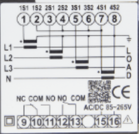
  • The 4 CT protection is connected according to the relay diagram. 
    When only L1, L2, L3 are connected to the circuit breaker for a 3 wire load which comprises of UPS, will it be better to use a 3 CT set up better or there is no significant difference at all?

  • now how are you combining those signals on pins 1, 3 5 and 7 to create the trip signal ?  - or does that happen in a pre-wired module.
    The short answer, assuming it is done correctly, that there is certainly no need to connect anything to ports 'N' or 'D'. But you may or may not need a representative current transformer winding between 7 and 8 of the same impedance as the ones between 1 and 8, 3 and 8, 5 and 8, depending how the 4 signals  are being combined.
    Mike.

Reply
  • now how are you combining those signals on pins 1, 3 5 and 7 to create the trip signal ?  - or does that happen in a pre-wired module.
    The short answer, assuming it is done correctly, that there is certainly no need to connect anything to ports 'N' or 'D'. But you may or may not need a representative current transformer winding between 7 and 8 of the same impedance as the ones between 1 and 8, 3 and 8, 5 and 8, depending how the 4 signals  are being combined.
    Mike.

Children
No Data