This discussion is locked.
You cannot post a reply to this discussion. If you have a question start a new discussion

Double wound safety transformer for EV supply.

Hi everyone, I have only posted once before so thanks to anyone who replies!


I am following on from the earlier "70 volt PEN conductor not allowed to exceed post", and looking into supplying a client with an electric vehicle power supply from a three phase isolating transformer BS 7671 722.413 (1.2): " The circuit shall be supplied through a fixed isolating transformer.."


The general consensus seems to be that an external IP box with an RCD (Type B) and a tethered lead is the standard to follow, and this may be the only option with a 230 volt domestic supply, but why not use a 3 phase 400 volt step down or tapped, safety double wound isolation transformer in a standard 100 -200 ampere or above industrial units/sheds?

( Subject to load and diversity).


The answer often stated when I have asked sparks/engineers is that in-rush current are too high but a type D CB BS 60898 will 'let through' the in-rush ( the transformer manufacturer agrees), and will still give at 5 seconds- (final circuit exceeding 32 A) 0.44 ohm EL ( 10oC) , so is achievable in many situations local to Birmingham.


I was then going to run a fused cable out to an external isolated IP 65 box with a Type 2 socket to IP44 or above ( 722.55.101).


Isn't it better to engineer a solution to the upcoming electric charger deluge, rather than buying (insert well known manufacturer name here), and lots of single phase loads usually dumped onto L1?


I would be interested in any thoughts or problems you may consider....


  • This Voltimum acticle makes some interesting points about mode 2 vs mode 3 charging approaches, especially in work environments (as well as some RCD & d.c. residual current issues).

       - Andy.
  • Andy

    In the separated system there is no danger from a charging live to chassis fault, unless there is also some way of accessing the neutral as well, which is connected to the PE connection and with my suggested arrangement will immediately trip the RCD. Remember nothing on the secondary side of the isolating transformer is connected to real earth, nor any Protective Earth connection. Moving to the block diagram, there is complete isolation between the charging supply and the charger output which is illustrated by the dotted line. This is the exact point at which double insulation may be applied, and would be conventionally done so in a normal class 2 power supply unit. If signalling is required along the earth wire (presumably the earth neutral loop), it also needs class 2 isolation but this is not beyond the wit of man to design. A worldwide standard needs to match all possible systems in use, it would be reasonable to have a list of who suggested what (daft) idea, and who voted it through!


    I am almost disgusted by Graham's comment that "its in product standard" or words to that effect, because a faulty product standard is no excuse to continue to use it, for example cladding for buildings!! The job of the standards committee is to produce proper and safe standards, and this should be completely isolated from any manufacturer or other political pressure. This also does not appear to be the case with BS7671. I have sat on standardisation committees in the past and a major issue has always been from manufacturers who are not prepared to change their own ideas, although they send often unskilled persons as representatives. A manufacturer trying to save tiny amounts of money in the design of the car is foolish beyond words, the reliability and safety of the car must be considered first, as both are the way reputations can be lost very quickly.
  • Electrically Modes 2 and 3 are very similar, in that the charger is in the car. Mechanically it looks quite different. The advantage of mode 2 is that the you take the bit that talks to the car to turn on the charger with you and can use an ordinary mains supply. The downside is you have no idea what protection or RCDs etc the building wiring provides in any given location.

    Nice image of the modes     


    Mode 4 (AC to DC conversion at the building) I see as more use for vans and lorries where more power is needed, and the chances of needing a charge in a strange place is less likely.


    I guess if the vehicle reverse charging idea (cars as generators) takes off, there will be another mode, where a box of magic allows your car to think it is plugged in so it will sync to a spoofed  grid, and work as a stand alone mains generator for people who are camping and so on and fancy a mains supply in the middle of a field. Closely followed by a jump lead mode for folk who over did it and can't get out of the field.


  • There was a great deal of push from the BBC about using the cars batteries for mains backup but in my view it is useless. The car battery will be cycled when not driving and will have reduced life. Clearly getting free batteries is of interest to renewables providers, but that is their job not the car owner. Having a car with a battery in an unknown charge state is also useless unless you live on a small island (as in the BBC piece), unless one can program the maximum and minimum status long before a journey is to be made. It is suggested that money will be paid for charge used by the grid, but this obviously needs to be at a very high rate to make it worthwhile for the car owner who needs a special car with reverse charge and a new battery more often. I doubt many people will be interested!

  • davezawadi:

    Andy

    In the separated system there is no danger from a charging live to chassis fault, unless there is also some way of accessing the neutral as well, which is connected to the PE connection and with my suggested arrangement will immediately trip the RCD. Remember nothing on the secondary side of the isolating transformer is connected to real earth, nor any Protective Earth connection. Moving to the block diagram, there is complete isolation between the charging supply and the charger output which is illustrated by the dotted line. This is the exact point at which double insulation may be applied, and would be conventionally done so in a normal class 2 power supply unit. If signalling is required along the earth wire (presumably the earth neutral loop), it also needs class 2 isolation but this is not beyond the wit of man to design. A worldwide standard needs to match all possible systems in use, it would be reasonable to have a list of who suggested what (daft) idea, and who voted it through!


    I am almost disgusted by Graham's comment that "its in product standard" or words to that effect, because a faulty product standard is no excuse to continue to use it, for example cladding for buildings!! The job of the standards committee is to produce proper and safe standards, and this should be completely isolated from any manufacturer or other political pressure. This also does not appear to be the case with BS7671. I have sat on standardisation committees in the past and a major issue has always been from manufacturers who are not prepared to change their own ideas, although they send often unskilled persons as representatives. A manufacturer trying to save tiny amounts of money in the design of the car is foolish beyond words, the reliability and safety of the car must be considered first, as both are the way reputations can be lost very quickly.


    If what you say is correct, then are you proposing BS 7671 prohibit EV charging equipment to current standards, which don't include an isolating transformer - or to PME systems in particular?


    Caravans and mobile/transportable units are also prohibited from connection to PME systems - does that make those "defective products" - definitely not! Also, doesn't stop homeowners plugging their caravans into their PME homes for many months of the year.


    There are definitely issues with isolating transformers in EV charging equipment - in particular, might effectively mean a CU change on occasion. In Engineering, there is often no "right answer".


    The situation with EV charging isn't unique with respect to differences between product standards and good installation practice [in a particular nation or region].

  • Graham

    It is easy to say that, but the car case is subject to a new(ish) standard, and some expect it to become common. I could treat it exactly like a caravan, but in reality it is probably more dangerous and TT is only a partial answer. The main difficulty is that cars are charged near PME earthed locations (garages, garden taps etc.), and at the same time the PME system is broken due to poor maintenance. Our answer is to make a fairly unsatisfactory set of regulations (I think most qualified people agree), and worry about the problems on a forum. Yes, the UK should permit only class 2 cars for new sales! The owners of the present vehicles would have the same problem that diesel drivers have, they changed the rules. They were changed to make the country safer, why not? CUs were changed to metal for "safety", why not cars?

  • davezawadi:

    Graham

    It is easy to say that, but the car case is subject to a new(ish) standard, and some expect it to become common. I could treat it exactly like a caravan, but in reality it is probably more dangerous and TT is only a partial answer. The main difficulty is that cars are charged near PME earthed locations (garages, garden taps etc.), and at the same time the PME system is broken due to poor maintenance. Our answer is to make a fairly unsatisfactory set of regulations (I think most qualified people agree), and worry about the problems on a forum. Yes, the UK should permit only class 2 cars for new sales! The owners of the present vehicles would have the same problem that diesel drivers have, they changed the rules. They were changed to make the country safer, why not? CUs were changed to metal for "safety", why not cars?


    If you have a proposal to either standards committee, I'm sure they'd be grateful to receive it.


    The PME system is NOT simply "broken due to poor maintenance"- it's a casualty in the changing face of the "fortuitous earthing system" that was the network of metal service pipes and certain distribution cable types.


    I'm not sure what "regulations" are unsatisfactory - I know of no specific legislation which covers this?


    I understand the "class II only" argument, but I'm not in a position to answer whether that's possible for specific reasons (e.g. plug-in hybrids, whether a protective conductor connection is preferred for static control etc.). Certainly, it is well outside the scope of BS 7671, because it's simply something someone will plug into an installation, it's not part of the "selection and erection" process?


  • Remember nothing on the secondary side of the isolating transformer is connected to real earth, nor any Protective Earth connection.


    In a conventional separated system that's of course true, but if I've understood Graham's description of what the CoP says correctly, in our case there would also be a deliberate connection between the separated "N" and the EVSE's PE terminal (or c.p.c) - in order to defeat the EV's earth loop check.  So what we have is at best a separated system with a first fault already present (or if you prefer an approximation to a TN system) - potentially referenced to true earth if any of the exposed-conductive-parts happen to be in contact with the ground (like that pole mounted EVSE pod). Yes the RCD should save the day but we're in effect relying on ADS then, not separation.


    Moving to the block diagram, there is complete isolation between the charging supply and the charger output which is illustrated by the dotted line.
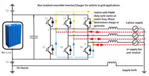


    In that diagram yes - however I'm given to understand that's not the case with all EVs - as some don't have an isolating transformer in that position, but rather like some 'transformerless' PV inverters - use a direct connection or dc-dc converter - for reasons of both weight and efficiency.  (I'll try to dig out some evidence for that.)


       - Andy.
  • Certainly transformerless  designs like this diagram are at least being prototyped, and mentioned in patents and R & D publications, if not in production machines yet.  During charging the battery is disconnected from the motors, and its wiring is then good enough to qualify as basic insulation. Rather like the old live chassis TVs of yore, without product standards, the techniques used are driven by price alone. I'm not that keen on the idea from an EMC perspective either, as the whole car now flaps up and down with the PWM fast edge rate, creating a whole RF comb of interference. It would of course be possible to add multi stage L-C filtering to the DC battery bus, but I can see it being value engineered away to a minimum if at all possible.


    The transistors switch at about 40-100KHz, but the duty cycle of that near square wave is modulated to give an average value that tracks the rise and fall of the mains cycles - with a mean voltage below it it to charge, and above it to generate AC from the battery, much like a VFD.

    1477b5a8651c9e6cad732c689ef91537-huge-reversible_inverter.png


  • Former Community Member
    0 Former Community Member
    Just throwing this idea out there, it has some clear limitations but it seems it could be a useful approach in some situations especially when the models of cars to be used are known.


    If we accept the load current argument from G12/4, and decide to make the charger no less safe then a bus shelter then it is not the load that is really of interest but the neutral current. There is the option of providing a 3-phase charge point and omitting the neutral entirely. The result is a charge point that will charge some, likely many models of cars, but (probably) doesn't comply fully with the charging point standards and there are some vehicles that will refuse to charge. It should however be safe and because no load current can flow in the neutral under any circumstances it is safe to connect to a PME earth without needing an unreasonably low electrode resistance.


    In terms of supported models I am pretty confident the Zoe (the only model I am really familiar with) will charge from such a supply. It initially does a L1-E loop test, which would pass. The three phases are hardwired to a 3-phase bridge rectifier in the charger and its normal behaviour is that if it sees appropriate L1-E volts but nothing on the rectifier output it closes a contactor shorting L3 to Neutral which allows single-phase charging (I would hope it also checks for L3-N volts first!). It is essentially a 3 phase charger by default with a link to make single phase charging work. This sort of behaviour is likely true across many models, most cars for the EU market support an 11 kW charging mode which is rare here; 16 A 3-phase (which they use where we would install a 7 kW single phase charger). Cars designed for the US market often only support AC charging at 240 V and below but where these are fitted with or adapted to type 2 connectors these are always connected L1 to N so wouldn't charge but would be safe.


    Limited in that a three phase supply is needed and not all models will charge, but no transformers are required and the earthing considerations are essentially the same as for a lamppost. It seems like it might be useful for workplace charging a fleet of Zoes or similar.