This discussion has been locked.
You can no longer post new replies to this discussion. If you have a question you can start a new discussion

Diesel Generator Fault Levels

Hello all,


I am looking to specify a temporary mobile diesel generator and as such looking into the disconnection times and the maximum fault current provided by the genset.

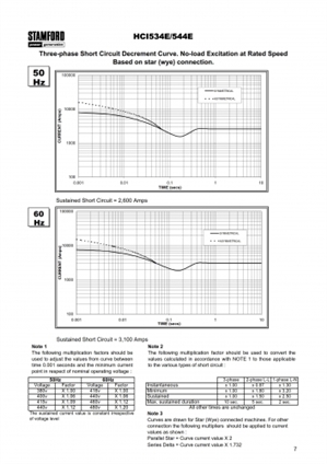
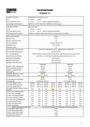
I have contacted a provider and got the specification of the alternator in their genset, images below of the fault current graph and the alternator per unit values.


I am looking into understanding what values to use. Am I correct in getting the sustained fault level and for an earth fault to apply the multiplication factor of 2.5 for sustained? I will make sure my disconnection times are less than the sustained maximum duration in order to not trip the generator breaker and loose all of the supply.


Alternator is 50Hz 415V
fc5681c638e7bada3947e466b96400fd-huge-newage-hci534e_1.jpg

3106a5e7994134e881a5487cbbe73194-huge-newage-hci534e.jpg


Parents
  • Unlike the street supply the output of a genset is a reactive impedance, and also a function of the state of load at the time of measurement. As a result, attempts to measure Zs in the normal way fail.

    To allow calculation, the wiggly curve is expressed as if it were a stair case with square corners, and flat regions.

    The results are given as multipliers, called by Cummins and others 'per unit factors' . So for example a genset configured for 100A, with a multiplier of 0.1, will supply 1000A into a dead short, until something changes.

    Typical multiplier values for gensets of some 100s of kVA or so are

    Sub-transient reactance X"d  0.09 – 0.17  First  6 cycles or so -determines maximum instantaneous current  and used for rating 'instant' breakers.

    Transient reactance X'd   0.13 – 0.20 6 cycles to 5 sec. current for short time delay circuit breakers.

    Synchronous reactance Xd 1.7 – 3.3 any time after 5 sec. This is the voltage droop, if there was no regulator to wind up the field and increase the torque and demand more fuel  i.e. woudl be the current without excitation support. In reality, the genset controller kicks in on this timescale.

    The Q factors are for  a step change in reactive load, and more use for determining the phase of the transients, and load steps for reactive loads.


    Your design current is 600kVA, 3 phase so I assume about 850A per phase L at full load.

    An LLL fault would heat the point of junction as if it was 2.5 times that.


    Your X'' d is 0.09. so an 11 fold multiplier into a dead short L-N , say 10kA , and then some more for luck, typically 2 for the worst case moment in the cycle to apply the short, as this gives an asymmetric transient.


    Your PSSC for rating your breakers could be 20kA.


    Is an LLL fault credible in your system ? If it is I'd consider checking if there are 'death or glory' fuses inside the genset.  three 1kA fuses would never go in normal operation, but would allow lower rated equipment downstream.


    However, what ADS is in the genset ? I'd expect the first item to limit the duration and let-through energy so that smaller (perhaps10kA) breakers can be used downstream.

    edit some background reading attached as an app note from Cummins.
Reply
  • Unlike the street supply the output of a genset is a reactive impedance, and also a function of the state of load at the time of measurement. As a result, attempts to measure Zs in the normal way fail.

    To allow calculation, the wiggly curve is expressed as if it were a stair case with square corners, and flat regions.

    The results are given as multipliers, called by Cummins and others 'per unit factors' . So for example a genset configured for 100A, with a multiplier of 0.1, will supply 1000A into a dead short, until something changes.

    Typical multiplier values for gensets of some 100s of kVA or so are

    Sub-transient reactance X"d  0.09 – 0.17  First  6 cycles or so -determines maximum instantaneous current  and used for rating 'instant' breakers.

    Transient reactance X'd   0.13 – 0.20 6 cycles to 5 sec. current for short time delay circuit breakers.

    Synchronous reactance Xd 1.7 – 3.3 any time after 5 sec. This is the voltage droop, if there was no regulator to wind up the field and increase the torque and demand more fuel  i.e. woudl be the current without excitation support. In reality, the genset controller kicks in on this timescale.

    The Q factors are for  a step change in reactive load, and more use for determining the phase of the transients, and load steps for reactive loads.


    Your design current is 600kVA, 3 phase so I assume about 850A per phase L at full load.

    An LLL fault would heat the point of junction as if it was 2.5 times that.


    Your X'' d is 0.09. so an 11 fold multiplier into a dead short L-N , say 10kA , and then some more for luck, typically 2 for the worst case moment in the cycle to apply the short, as this gives an asymmetric transient.


    Your PSSC for rating your breakers could be 20kA.


    Is an LLL fault credible in your system ? If it is I'd consider checking if there are 'death or glory' fuses inside the genset.  three 1kA fuses would never go in normal operation, but would allow lower rated equipment downstream.


    However, what ADS is in the genset ? I'd expect the first item to limit the duration and let-through energy so that smaller (perhaps10kA) breakers can be used downstream.

    edit some background reading attached as an app note from Cummins.
Children
No Data