This discussion has been locked.
You can no longer post new replies to this discussion. If you have a question you can start a new discussion

Dodgy garage installation - borrowed neutrals?

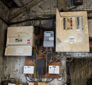
This photo appeared in a car advert which was mentioned in a motoring forum.


The three lines all appear to make their way to the 3-phase board, but I cannot quite see why is happening to the neutrals.


Presumably the meter fitters were content that all was in order, although I suppose that the supplier's' principal concern is billing.


Would nobody give it a satisfactory EICR?
fe04cba68d8023216b9d65ea7caac269-huge-8a324a46-e898-499a-9e06-beead3f8b6bf.jpg

Parents
  • There is a fairly weedy looking cable going down to the inverted service head, from which it appears that there are two Ns and one L. The L goes to the bottom L meter whose output goes to the Henley block which is partially obscured by DB3's door. One tail from the block goes to DB1 - let's call that L1. N from the same meter goes to DB3 - so far so good!


    A live tail enters the top fuse and goes to the top meter. It goes from the Henley block to DB1 - let's call that L2. There may be another line from there to God knows where.


    The third tail goes to the middle fuse and appears to go to the bottom right meter from which there is another tail to DB1 - that's L3. So we have 3 live tails to DB1. So the line conductors seem to be fairly straightforward, but I cannot see any grommet at the entry to DB1.


    The only N tail goes to the upside-down service head. There appear to be 2 downstream N tails. I think that one goes to the bottom right meter and the output from there goes to the bottom left meter and then onto DB3. That has been metered twice. The other N goes to the top meter and the output passes through a Henley block (why?) and onto DB1. So the top meter records L2 and N for DB1.


    There appears to be a second line output from the bottom right meter. Again, it isn't clear where it goes or where it's N partner originates.


    The circuits appear to be complete, and (save for the cable entry into DB1) it is not obviously non-compliant, but I wouldn't put my name to that sort of workmanship.


    If the L and N are not balanced, what does the meter measure?


    Did anybody notice the on/off labels on DB1?


Reply
  • There is a fairly weedy looking cable going down to the inverted service head, from which it appears that there are two Ns and one L. The L goes to the bottom L meter whose output goes to the Henley block which is partially obscured by DB3's door. One tail from the block goes to DB1 - let's call that L1. N from the same meter goes to DB3 - so far so good!


    A live tail enters the top fuse and goes to the top meter. It goes from the Henley block to DB1 - let's call that L2. There may be another line from there to God knows where.


    The third tail goes to the middle fuse and appears to go to the bottom right meter from which there is another tail to DB1 - that's L3. So we have 3 live tails to DB1. So the line conductors seem to be fairly straightforward, but I cannot see any grommet at the entry to DB1.


    The only N tail goes to the upside-down service head. There appear to be 2 downstream N tails. I think that one goes to the bottom right meter and the output from there goes to the bottom left meter and then onto DB3. That has been metered twice. The other N goes to the top meter and the output passes through a Henley block (why?) and onto DB1. So the top meter records L2 and N for DB1.


    There appears to be a second line output from the bottom right meter. Again, it isn't clear where it goes or where it's N partner originates.


    The circuits appear to be complete, and (save for the cable entry into DB1) it is not obviously non-compliant, but I wouldn't put my name to that sort of workmanship.


    If the L and N are not balanced, what does the meter measure?


    Did anybody notice the on/off labels on DB1?


Children
No Data