This discussion has been locked.
You can no longer post new replies to this discussion. If you have a question you can start a new discussion

Dodgy garage installation - borrowed neutrals?

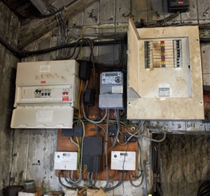
This photo appeared in a car advert which was mentioned in a motoring forum.


The three lines all appear to make their way to the 3-phase board, but I cannot quite see why is happening to the neutrals.


Presumably the meter fitters were content that all was in order, although I suppose that the supplier's' principal concern is billing.


Would nobody give it a satisfactory EICR?
fe04cba68d8023216b9d65ea7caac269-huge-8a324a46-e898-499a-9e06-beead3f8b6bf.jpg

  • I am rather left wondering what we are seeing here - I see a single phase cut out with one fused live and a neutral that is not the normal way up, and 2 single pole fuses in the middle of what looks like meter tails coming in from somewhere else. This is not a supply upgrade from 1 phase to 3  in quite the way it would be done around here. I'm hoping there is a proper DNO owned 3 phase incomer somewhere else, and this is only secondary metering, however  the fact that what I assumed were post meter Henley blocks are sealed, and some of  ones that appear to be pre-meter  do not appear to be, I'm far from certain about which way things are actually being used.

    One could be forgiven for a sharp intake of breath, and a sound like 'eek'.

    Some tidying up required at the very least.


  • I don't think those neutrals were so much borrowed as stolen down a dark alley!
  • Most of the confusion appears to be on the supply side of the meters.

    Also the 2 Henley boxes at odd angles appear to be something to do with the fitting of a new meter too.

    The top left DB's cover obscures the wiring as do the "items" on the shelf below.
  • We have three phases, three single phase meters, (one AMR meter, two classic meters.) One meter is feeding one single phase board and one phase of the three phase and neutral board. the other two meters are each feeding the remaining other two phases of the three phase and neutral board. 


    Regards, UKPN.

  • Mapj where ate the 2 single pole fuses? Are they the black blocks near the top of the foto?


    Yes - the things looking like an oversized Henley blocks to the left of the grey meter are, I think, 100A fuse holders, and appear to be the other 2 phases coming in from stage left, but as I said before that looks like meter tail, so somewhere it must join to some sort of 3 phase incoming point, either underground, or maybe they crimp onto the tails of a set of ageing overhead singles - but then I'd expect the other phase to  be the same, this looks more of an afterthought.


  • As much as it pains me I have to agree with UKPN on this one, the property was most likely originally a single phase supply, then it has been upgraded to 3 phase. The top fuse is supplying the AMR meter which in turn is supplying one phase of the 3 phase board, The middle meter is supplying the bottom right hand meter which is supplying a single phase board  (not quite in picture) and another phase of the 3 phase board, the original supply is feeding the bottom left hand meter (you can still see the original top fixing screw for the original meter) which in turn is supplying DB3 and the last phase to the 3 phase The left hand neutral from the lower service head is in terminal 3 of the right hand meter, terminal 2 of the right hand meter is then going to the left hand meter wich in turn is going to a block underneath the cover of DB3, the right hand neutral from the service head is going to the AMR meter, that in turn is going to the block above the right hand meter. Kelly yes it looks untidy, but who would pay to tidy it up, as it is not unsafe.
  • There is a fairly weedy looking cable going down to the inverted service head, from which it appears that there are two Ns and one L. The L goes to the bottom L meter whose output goes to the Henley block which is partially obscured by DB3's door. One tail from the block goes to DB1 - let's call that L1. N from the same meter goes to DB3 - so far so good!


    A live tail enters the top fuse and goes to the top meter. It goes from the Henley block to DB1 - let's call that L2. There may be another line from there to God knows where.


    The third tail goes to the middle fuse and appears to go to the bottom right meter from which there is another tail to DB1 - that's L3. So we have 3 live tails to DB1. So the line conductors seem to be fairly straightforward, but I cannot see any grommet at the entry to DB1.


    The only N tail goes to the upside-down service head. There appear to be 2 downstream N tails. I think that one goes to the bottom right meter and the output from there goes to the bottom left meter and then onto DB3. That has been metered twice. The other N goes to the top meter and the output passes through a Henley block (why?) and onto DB1. So the top meter records L2 and N for DB1.


    There appears to be a second line output from the bottom right meter. Again, it isn't clear where it goes or where it's N partner originates.


    The circuits appear to be complete, and (save for the cable entry into DB1) it is not obviously non-compliant, but I wouldn't put my name to that sort of workmanship.


    If the L and N are not balanced, what does the meter measure?


    Did anybody notice the on/off labels on DB1?


  • most if not all modern meters only need the though connection in the live pole to sense current, this is them multiplied by the voltage from the outbound live side to the neutral  to get watts- the neutral has 2 terminals to allow loop-through wiring, but is in effect one terminal  for voltage sensing.

    The meter will read correctly with a 3 wire connection L in, L out, and N.  However, a 3 wire connection is frowned upon,not least because it can conceal an  abstraction mechanism - imagine if the neutral connection were high impedance. This installation may work OK, but it is very poor practice
  • I agree with Mike - 'looping' N though two or more meters doesn't affect the measurements - and was commonly seen in olden days when 3-phase supplies were metered using three separate single phase meters.


    So not borrowed N, just a common N for a single 3 phase circuit.


    Curiously, BS 7671 wouldn't have an issue with it anyway even if it was borrowed and not on the supplier's side, as (for reasons I've still yet to fathom) 314.4 only applies to final circuits.


       - Andy.