This discussion has been locked.
You can no longer post new replies to this discussion. If you have a question you can start a new discussion

LM 3914

Hello,

anyone into electronics to help me (I have some suspects).


I am having trouble with LM 3914/5/6

I get the current program of LEDs by making path to ground 0V from Pin 7.

Pins 7 & 8 give use approx 1.25 volt ref

It`s the pin 6 & pin 4 Rhi and Rlo bits in order to get values of other than the supply lines.

i.e if we put in two resistors R1 & R2 from pin 7 to 0V and calculate the voltage at the junction then we could use this as a hi or low I think but what about the other (to get a hi and a lo) .


Then methinks factor in the internal comparitor divider chain into these figures to see if a significant variation occours .


I initially want to prog my LEDs to say 10 or maybe 15mA current and the hi and low volt comparisons say 1.8v to 4.0v.

Thanks
  • Aha the cascadable bar  graph chip from nat semi - a venerable piece of silicon indeed. Know it well.


    If you are using the internal refernce to also set the full scale voltage of the graphs, as well as the  LED current, you need to realise in the app note circuit the ratio of the resistors sets the voltage, and the current through them sets the LED brightness, as it is the  load on the reference voltage regualtor that sets the LED brightness.


    The high and low voltages for the comparators can either both or neither be derived from the reference regulator by resistive division.

    Can you put up a sketch of what you have so we can talk about things with names - R1 R2 or whatever, or it will be confusing and probably wrong.

    I'm off to lunch now but back in ~ 90-mins, and I can look the chip datasheets up then so I have the right pin nos and voltages.


  • Any help: LM 3914 datasheet?

      - Andy.
  • Ha two first line suspects answered already, thanks guys.


    Yes Mapj I already know that. It`s just adjusting my head around it is the problem

    Truth is, about 30 years ago I built a gadget for some plumbng heating bods for checking gas valve solenoids but me poor heed has got older and more cluttered and worn out since. I think I`d be ok setting the high by calculating current thru resistors it`s just starting at non zero that`s giving me a headache.


    AJJ, Yes thanks I have the data sheet it`s just following it.


    I will make a sketch to let you know what I`m thinking and you`d probably spot where I`m wrong (or right even) .

    Cheers guys.
  • Ok if you want 10mA though the LEDS then you need 1.25k between the Ref out and the Ref in (1.25V accross 1.2k = 1mA, but internal current mirrors put 10 times this down each LED)


    Now to set the top end to 4V, you need the total chain to be 4k, (1mA remember) but to set low to 1.8V that needs to be 1.8k to ground, then 1k up to the ref in and 1.25k to the ref out.


    Internally the chip is about 10k  (8 to 17k according to that data sheet )between the low and high ends of the internal resistor ladder, so the error is ~ 10%.

    If you need better than please  note that the tolerance on the on chip resistors, and on the voltage of the reference (1.2-1.34 V) is not that great, so you may need trimmer resistors to fine tune for each chip if the application is that level  critical.
  • OK,

    R3 + R4 must drop 1mA to 0V therefore R3 = 1.25V/).001A = 1K25

    Therefore R2 + R3 + R4 - 1K8 to make Rlo 1.8V at 1mA

    Therefore R2 = 1K8 - 1K25 = 550R

    R1 therefore needs to lift 4.0v - 1.8v = 2.20v  at 1mA therefoe 2K20

    If R3 = 1K25 then R4 can be zero (Why did I put it in?)

    I`m assuming that once we set the current on R3 then the same current runs on R2 and R1(with the chain of 10K in parallel).


    finally 10K in parallel with 2K20 gives 1K803 so we need to up R1 to recalculate this 2.20 volt drop.


    PS I`d done this before I got your reply Mapj so I`ll have a look at that shortly thanks


  • Not sure I follow your diagram. I'll sketch something tonite.
  • Cheers Pal, that is a coincidence, I`m not sure that I follow my diagrams either LOL. I am confusing meeself meethinks
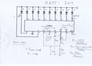
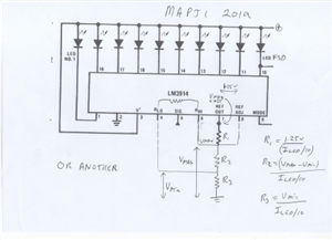
  • Sorry for delay, busy day involving a defective boiler. two bias methods to compare, one better for low level signals, and another better for bigger signals as the REF voltage gets uncomfortably high if the upper level is more than say 5V. E and OE as they say..


    Depends a bit on your supply voltage as well as range of signals.

    Given the tolerance between identical chips of the 1.25 V reference, and the variation of the built in resistor chain, if more than 10% precision is needed, then it will need trimmer resistors that are tuned up individually for each chip. (a trimmer of say 470 ohms in series with 1K for a nominal 1.2k gives a well centred adjustment, and cannot do damage if wound to minimum)

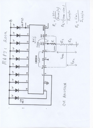
    Given that, for fixed levels the nearest 5% resistors will be as good as some funny value. Hope you can read the writing for the formulae

    Not that actually the nominal ratio of LED current to reference chain current is more like 12.5 than 10, as I drew this without looking at the book, sorry, but it matters not a lot - the resistor ratios are what sets the max and min thresholds.

    ONE WAY


     OR ANOTHER
    59979cdedf60d84d9047b03f325988fa-huge-lm3914002.jpg

  • Thanks Mapj1 you`ve made it so simple. Guerss I was having a senior moment trying to complicate it.

    All those years ago I did build one for the heating engineers to test gas boiler thermocouple voltage.

    I had it to read from zero to good (say 30mV or some such figure) and with a switch to put a dummy load across the thermocouple to represent a gas valve solenoid.

    Put magnet feet on so they could attach it to a boiler.


    Even made a simple calibrater, 9v PP3 battery dropping the supply across a load resistor and zener diode in series. A preset across the zenner to give a ref output voltage for calibration. Once set using a multimeter the calibrater was left with the tester.


    Fasten thermocouple output to croc clips , light boiler, observe bargraph display. Repeat with dummy load switched in. It gave a good indication of how the thermocouple was acting. Not only by voltage attained but rate of rise too. Gave a good visual indication.

    I know they used it for some years. I think I`ll ask them if they still got it.


    Note this was acting from 0V to full expected reading.

    On my application it was the both high AND low references that got me fuddled.

    Like I said - senior moment.


    Thanks Mapj1 for your help, much appreciated. Thanks AJJ for your reply too.


    Mapj1, I`m considering rplacing resistors with presets, I`ll calculate the ideal resistor values then subtitute with presets. That way I could tweek not only the LED current but the high and low parameters. In this application it`s to give an easy visual indication, some metres away, of the output signal from a photo electric external beam detector rather than using a multimeter. But I can envisage other uses too.


    I knew my brethern would enlighten me. ?
  • rotated the images and reloaded this morning, as the forum SW cant handle that.
    070fcf7c98c5fa66f282ae93d2f8d833-huge-lm3914001.jpg


    and again


    828ede0812387ddff8c8818c15587251-huge-lm3914002.jpg


    These formulae ignore the loading of the in-chip resistors on the ladder values, but the current in the main branch will be 1mA or so for 10mA LED, and the ladder is  going to be a couple of hundred uA or so, an error of 10% ish. The middle resistor needs increasing by a similar fraction to compensate.