This discussion has been locked.
You can no longer post new replies to this discussion. If you have a question you can start a new discussion

LM 3914

Hello,

anyone into electronics to help me (I have some suspects).


I am having trouble with LM 3914/5/6

I get the current program of LEDs by making path to ground 0V from Pin 7.

Pins 7 & 8 give use approx 1.25 volt ref

It`s the pin 6 & pin 4 Rhi and Rlo bits in order to get values of other than the supply lines.

i.e if we put in two resistors R1 & R2 from pin 7 to 0V and calculate the voltage at the junction then we could use this as a hi or low I think but what about the other (to get a hi and a lo) .


Then methinks factor in the internal comparitor divider chain into these figures to see if a significant variation occours .


I initially want to prog my LEDs to say 10 or maybe 15mA current and the hi and low volt comparisons say 1.8v to 4.0v.

Thanks
Parents
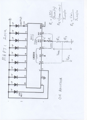
  • Sorry for delay, busy day involving a defective boiler. two bias methods to compare, one better for low level signals, and another better for bigger signals as the REF voltage gets uncomfortably high if the upper level is more than say 5V. E and OE as they say..


    Depends a bit on your supply voltage as well as range of signals.

    Given the tolerance between identical chips of the 1.25 V reference, and the variation of the built in resistor chain, if more than 10% precision is needed, then it will need trimmer resistors that are tuned up individually for each chip. (a trimmer of say 470 ohms in series with 1K for a nominal 1.2k gives a well centred adjustment, and cannot do damage if wound to minimum)

    Given that, for fixed levels the nearest 5% resistors will be as good as some funny value. Hope you can read the writing for the formulae

    Not that actually the nominal ratio of LED current to reference chain current is more like 12.5 than 10, as I drew this without looking at the book, sorry, but it matters not a lot - the resistor ratios are what sets the max and min thresholds.

    ONE WAY


     OR ANOTHER
    59979cdedf60d84d9047b03f325988fa-huge-lm3914002.jpg

Reply
  • Sorry for delay, busy day involving a defective boiler. two bias methods to compare, one better for low level signals, and another better for bigger signals as the REF voltage gets uncomfortably high if the upper level is more than say 5V. E and OE as they say..


    Depends a bit on your supply voltage as well as range of signals.

    Given the tolerance between identical chips of the 1.25 V reference, and the variation of the built in resistor chain, if more than 10% precision is needed, then it will need trimmer resistors that are tuned up individually for each chip. (a trimmer of say 470 ohms in series with 1K for a nominal 1.2k gives a well centred adjustment, and cannot do damage if wound to minimum)

    Given that, for fixed levels the nearest 5% resistors will be as good as some funny value. Hope you can read the writing for the formulae

    Not that actually the nominal ratio of LED current to reference chain current is more like 12.5 than 10, as I drew this without looking at the book, sorry, but it matters not a lot - the resistor ratios are what sets the max and min thresholds.

    ONE WAY


     OR ANOTHER
    59979cdedf60d84d9047b03f325988fa-huge-lm3914002.jpg

Children
No Data