This discussion has been locked.
You can no longer post new replies to this discussion. If you have a question you can start a new discussion

Wiring 10 vector heaters supplied by 10mm cable.

Former Community Member
Hi,


Whilst on site a few weeks ago, I noticed an electrician wired 10 vector heaters onto a 10 gangway switch.

​​​​each of the switches turned each of the heater's on. 

however, all these switches were supplied by the 10mm cable I was running above the ceiling tiles. 

Now I noticed each heater had a power rating of 2500 watts, 


So assuming all the heater's were turned on, and given the kind of premises it was, all the heater's would be on if used, that would have been a total of 25000 watts supplied by a 10mm cable. 


I'm just confused as to how he wired it,

Im pretty sure they were wired parralel, as each heater had it's own flex going straight to the switch board. Can anyone can help with a wiring diagram. It's really been bugging me.
  • Moses, this has clearly bothered you otherwise you would not have posted. You have referred to "the cable" more than once, which indicates that you only pulled in one cable, presumably a single.


    I think that your concern is justified, but it is difficult to see what you can do about it now. Is there anything that we can do to help?
  • Former Community Member
    0 Former Community Member
    Initially, I thought this was something new I could learn, that's why I was asking for a wiring diagram. But like you said I was a bit concerned. I think now, seeing multiple comments, I can't really tell until I actually open it up and see, which is not going to happen.


    The cable was a 10mm twin and earth,

    Thanks everyone for your input, I have learnt something new from most of the comments.
  • Former Community Member
    0 Former Community Member
    What would be interesting to know, as I'm still learning as a level 3 trainee, is there a way to put 10 heater's with a total  power Rating at 25000 Watts in parralel organized into a single 10 gangway switch Panel. 


    ​​​​​​Apologies for any inconvenience, but a wiring diagram is what would stick in my head

  • Moses:

    What would be interesting to know, as I'm still learning as a level 3 trainee, is there a way to put 10 heater's with a total  power Rating at 25000 Watts in parralel organized into a single 10 gangway switch Panel. 


    ​​​​​​Apologies for any inconvenience, but a wiring diagram is what would stick in my head


    In practice no, ten heaters each with a loading of 2.5Kw can not be used simultaneously on a single 10mm cable.

    It might in theory be possible with some non standard and higher supply voltage, but in practice the heaters are almost certain to be 230/240 volt.

    It could be done with three phase, but O/P has stated single phase.

    It might just be doable with very hot running MICC cable, but O/P has stated twin with earth.


    It is of course possible to connect ten heaters on the assumption that they wont all be used at the same time, but I would be very doubtful about proceeding thus. If ten heaters are available, then someone might turn them all on !

    Are these space heaters or water heaters ? If they are very small instantaneous water heaters as used for hand washing in toilets, then it might be acceptable since they are only used briefly and the chance of all being used together is very small.

    If space heaters, then I perceive a significant risk of overloading the cable.


    Finally, from where is this supply to be obtained ? The total loading is over 100 amps. Very few single phase supplies exceed 100 amps, and it is probable that other loads will be required also. Even with a large 3 phase supply, it would be rather odd to add over 100 amps to one phase.
  • Former Community Member
    0 Former Community Member
    They're convector heater's, they use to be on a ring final, but installer replaced them with independent fused switches with a set of main switches all organized together. 

    the supply is single phase from a standard wylex consumer unit, this premises has multiple consumer unit's each with it's own feed. 


    Thanks for your answer

  • they use to be on a ring final


    That makes it sound like the load isn't (too much) over 32A - or maybe they had problems and the 10mm² is an upgrade to something slightly larger.


    but a wiring diagram is what would stick in my head
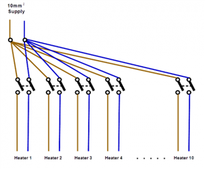


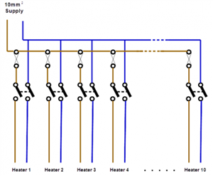
    Maybe this would be a start... in theory the basics are simple enough - one switch per heater all wired in parallel. (I've shown them as double pole, but single pole switches and a solid N connection might do if you didn't need N to be isolated.) So something like this:

    d15f963afe8231874d222bcd04eff91b-huge-basicswitches.png


    Obviously there'll be c.p.c.s in there as well, but I've omitted them for clarity (or due to laziness!)


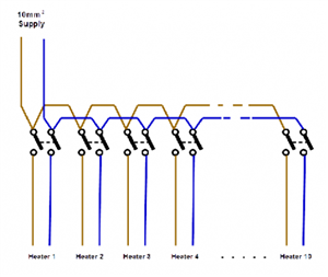
    There's an obvious problem with that layout though, as grid switch terminals won't accept anything as large as a 10mm² (let alone looped so two in a terminal) - so it would need modifying slightly - one way of doing that would be to terminate the 10mm² into a big terminal and take one wire from there to each switch.

    c23967d87f7518626b65b90c66f70f5d-huge-basicswitchesterminal.png


    Then there's likely the problem with fusing - as we're going from a large conductor (with presumably a large fuse) to smaller ones for each individual heater (and associated switch) - there's a real possibility that the protection for the 10mm² wouldn't provide protection for the smaller conductors. So ideally you'd have one fuse (or MCB) per heater and so your diagram would look something like this:

    8c70a0faef9e0101d504ab63a19e3a6b-huge-basicswitchesfused.png


    In fact, almost as if the top half were a distribution board (or consumer unit)...


    There are a lot of other possibilities, (in theory it is permitted to omit fault protection for short lengths of conductor under certain circumstances, which might allow for slightly different arrangements for example) - but hopefully that gives you an idea at least.


      - Andy.
  • In amongst all the issues you have to consider the size and ratings of the terminals in the fittings. 

    I would install a substantial distribution circuit to a consumer unit or distribution board that is rated to carry the full load with a 100 amp main switch and then run each final circuit from there with its own 16 amp MCB and a double pole isolation switch are the location of each heater. 


    At least that set-up won't burn the building down, it does of course require a adequate supply at the intake. 


    Andy Betteridge