This discussion is locked.
You cannot post a reply to this discussion. If you have a question start a new discussion

Max Zs BS7671 17th Edition / Guidance Note 3 Inspection and Testing

Former Community Member
Hello,


There seems to be some slight differences with regards to acceptable Zs values when comparing the two documents BS7671 17th Edition A3 and Guidance Note 3 Inspection and Testing 17th Edition A3.


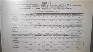
For example table 41.3 from BS7671 17th Edition A3 states:


0.4sec trip D6A = 1.82 Ω


Adjusted to 80% as per appendix 14 = 1.456 Ω


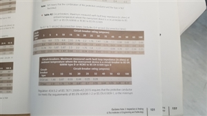
However page 121 from Guidance Note 3 Inspection and Testing 17th Edition A3 states:


0.4sec trip D6A = 1.46 Ω


These two documents are produced by IET. Guidance Note 3 Inspection and Testing 17th Edition A3 is rounding up Zs values above the maximum allowable values detailed in BS7671 17th Edition A3, why is that ?


ba51c8f3cf43a4eb3610fe4e2008860e-huge-20190722_083125.jpg


5d6415d8285e515a6e1d04f5ef5fb4b8-huge-20190722_083103.jpg


Parents
  • Former Community Member
    0 Former Community Member
    mapj1


    Surely they should round down Zs values in the Guidance Note 3 Inspection and Testing 17th Edition A3 rather than rounding the figures upwards.


    Adjusted to 80% as per appendix 14 = 1.456 Ω


    Round down to 2 decimal places = 1.45 Ω


    All digital Fluke and Megger loop impedance meters I have used are accurate enough to tell the difference between 1.45 Ω and 1.46 Ω . 


    Taking into account all that we know about breaker tolerances and circuit load/voltage variations, if something is defined as the maximum then surely it should it should never be acceptable to have a value higher than the maximum as far as the regs are concerned. 


    I see no logical reason for the IET to round the figures upwards instead of rounding the figure downwards if wanting to display to 2 decimal places.


Reply
  • Former Community Member
    0 Former Community Member
    mapj1


    Surely they should round down Zs values in the Guidance Note 3 Inspection and Testing 17th Edition A3 rather than rounding the figures upwards.


    Adjusted to 80% as per appendix 14 = 1.456 Ω


    Round down to 2 decimal places = 1.45 Ω


    All digital Fluke and Megger loop impedance meters I have used are accurate enough to tell the difference between 1.45 Ω and 1.46 Ω . 


    Taking into account all that we know about breaker tolerances and circuit load/voltage variations, if something is defined as the maximum then surely it should it should never be acceptable to have a value higher than the maximum as far as the regs are concerned. 


    I see no logical reason for the IET to round the figures upwards instead of rounding the figure downwards if wanting to display to 2 decimal places.


Children
No Data