This discussion is locked.
You cannot post a reply to this discussion. If you have a question start a new discussion

Max Zs BS7671 17th Edition / Guidance Note 3 Inspection and Testing

Former Community Member
Hello,


There seems to be some slight differences with regards to acceptable Zs values when comparing the two documents BS7671 17th Edition A3 and Guidance Note 3 Inspection and Testing 17th Edition A3.


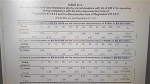
For example table 41.3 from BS7671 17th Edition A3 states:


0.4sec trip D6A = 1.82 Ω


Adjusted to 80% as per appendix 14 = 1.456 Ω


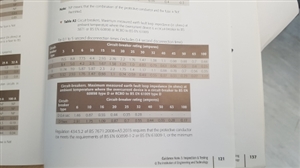
However page 121 from Guidance Note 3 Inspection and Testing 17th Edition A3 states:


0.4sec trip D6A = 1.46 Ω


These two documents are produced by IET. Guidance Note 3 Inspection and Testing 17th Edition A3 is rounding up Zs values above the maximum allowable values detailed in BS7671 17th Edition A3, why is that ?


ba51c8f3cf43a4eb3610fe4e2008860e-huge-20190722_083125.jpg


5d6415d8285e515a6e1d04f5ef5fb4b8-huge-20190722_083103.jpg


  • In the sense that one is not  re-print of the other, they are not the same,  however, for the example you highlight the difference is 0.4%. As most real meters measure these low resistances to at best a few %, and then one or two flickers of the last digit. So as far as any meter reading is concerned, they are the same. 

    There is a large element of "measure with a micrometer, mark in chalk, cut with an axe" about the decision about what is an acceptable Zs level for a given breaker anyway, in the sense it is a very accurate calculation of something that does not happen - for example if faults actually were zero resistance, they would not actually  dissipate any energy and would not get hot - as I'm sure you realise looking at any burnt end will confirm this is not the case ?.


    Working the other way, no breaker is made spot on the limit of the breaking range, so when we assume 20 times the rating for a D type, we are being unduly pessimistic, on average one out of the box will be more like 15. But that may vary with batch and the age of the breaker, as the moving parts oxidise and get a bit stiffer.


    so 20* 6A is 120A - so to be safe assume no instant break unless the current is >120A , probably similar magnetic parts as a 32A B type.

    Then we say what shall we assume about the supply - perhaps 230V and 20% margin for bad luck ? 230/120 is 1.916666  and 20% off for luck is 1.533333 . (when did you last see exactly 230V... )


    But should we assume that we are testing cold, but the cable may be hot when the fault occurs, and allow a bit more - and how warm was it when you tested it ? Then during fault, is the CPC already hot as well or just the live cores - probably depends on the arrangement - steel conduit may have a cold CPC, for T and E the CPC is more thermally in contact with the live cores.


    Also for the D type some times the thermal part gets there at about the same time as the magnetic, depending on the ambient temperature ,and so maybe we have to assume the breaker is cold and the cable hot.


    And now the part of the resistance of the street main, and the real external voltage, will depend on other user's loads, and may change without warning if the DNO needs to change a transformer or make a repair to cables in the street.


    My point is not that we need to know all this, usually we cannot hope to, but more that if your design is close to the limit, and relies on a change of less than 5000 parts per million to put it one side of the line or the other, then it does not matter, as the last digits on the tester are about as helpful as a fruit machine. The only safe conclusion is that it is a marginal design, and may or may not meet the advice of BS7671,  depending who tests it and what the weather is on the day, and how clean his meter probes are. A 6A circuit  is unlikely to become immediately  dangerous for want of a few milli-ohms, and there is no need to be alarmed that a slightly different set of assumptions and rounding is not identical.


  • Put more simply, my tester measures to +/- 0.5% +/- 1d; or +/- 1% +/- 1d depending upon the range selected and gives a reading to two decimal places.


    So if it gives me a value of 1.46 Ω that could be anywhere from 1.45 Ω - 0.5% = 1.44275 Ω to 1.47 Ω + 0.5% = 1.47735 Ω, which easily includes your calculated value of 1.456 Ω.


    Note also that the values in Table 41.3 have been rounded to 2dp. The last column gives the calculation, so for example, the calculation for a 25 A Type D MCB gives 0.437 Ω, which has been rounded up to 0.44 Ω.
  • Former Community Member
    0 Former Community Member
    mapj1


    Surely they should round down Zs values in the Guidance Note 3 Inspection and Testing 17th Edition A3 rather than rounding the figures upwards.


    Adjusted to 80% as per appendix 14 = 1.456 Ω


    Round down to 2 decimal places = 1.45 Ω


    All digital Fluke and Megger loop impedance meters I have used are accurate enough to tell the difference between 1.45 Ω and 1.46 Ω . 


    Taking into account all that we know about breaker tolerances and circuit load/voltage variations, if something is defined as the maximum then surely it should it should never be acceptable to have a value higher than the maximum as far as the regs are concerned. 


    I see no logical reason for the IET to round the figures upwards instead of rounding the figure downwards if wanting to display to 2 decimal places.


  • Mike M:

    All digital Fluke and Megger loop impedance meters I have used are accurate enough to tell the difference between 1.45 Ω and 1.46 Ω .


    That is not correct for the reason that I have given above.


    Also if you measure the Zs of a given circuit, it will not give the same reading every time. For example, I use a socket in my workshop for checking my MFT. The mean reading is 0.85 Ω with a standard deviation of 0.04 Ω.


    Precision in measurement is quite a complicated matter.

  • Former Community Member
    0 Former Community Member
    Chris Pearson‍ 


    That's very presumptuous of you considering you don't know what meters I have used. 


    Once again taking into account all that we know about tolerances and circuit variations, if something is defined as the maximum then surely it should it should never be acceptable to have a value higher than the maximum as far as the regs are concerned.
  • The appendices to the regs and the guidance notes are just that, guidance. 

    In the end  the design is something for which the designer is responsible for, and part of that is to decide if you cone in  or cone out when you look at the test instrument accuracy, you may prefer to set your own tighter limits, or you may know more about the installation and set wider.

    .For the reasons given in my first response, for engineering purposes, I see two indentical numbers, just with different no.s of redundant trailing digits.


  • I believe Megger recommends as a general rule,  taking 3 readings when doing loop impedance measurements and then using the average value as some supplies can be quite volitile in their waveforms Therefore accuracy to more than 2 decimal places is often very hard to justify in the field as opposed to on paper.


    Legh

  • Once again taking into account all that we know about tolerances and circuit variations, if something is defined as the maximum then surely it should it should never be acceptable to have a value higher than the maximum as far as the regs are concerned.


    Have you considered the possibility that the printed values in BS 7671 have been rounded down to 2 decimal places? Calculations based on the (slightly higher) original value and then also rounded down might give the kind of result you observe?


       - Andy.
  • Former Community Member
    0 Former Community Member
    mapj1 


    People are well aware that guidance notes are for guidance. However the guidance notes should not be contradicting the regs, especially when they are both produced by the IET.


    To follow your train of taught lets run the calculation from start to finish without limiting to 2 decimal places.


    Table 41.3 from BS7671 17th Edition A3 requires:


    0.4sec trip D6A = (230 x 0.95 / 20x6) = 1.8208333333 Ω


    Adjusted to 80% as per appendix 14 = 1.4566666667 Ω


    Page 121 from Guidance Note 3 Inspection and Testing 17th Edition A3 states:


    0.4sec trip D6A = 1.46 Ω


    The problem in "engineering" terms or any other terms for that matter is 1.4566666667 Ω does not equal 1.46 Ω.


    If IET are stating values are the maximum then they should not be contradicting in the same breath by rounding up Zs figures above the maximum.


    In any case I have not heard a valid reason as to why the IET would round up Zs values above the maximum allowed by BS7671 instead of rounding them down if they want to display them to 2 decimal places.


    Thanks for the feedback.


  • 1.4566666667 Ω does not equal 1.46 Ω.


    I beg to differ. The difference is less than nothing in that application,or if you prefer language with rather more mathematical rigour, it is less than the combination of instrumentation error and experimental variation and the results are statistically indistinguishable.


      I suggest you go and measure Zs on  a real system with a real meter early in the morning, then go out for lunch and polish the meter probes and re-test with the same meter at the same point in the afternoon. The two readings will be both as valid, but are unlikely to be the same in all digits. As an aside what meters do you suggest with this accuracy (not precision) ? Note that two half lengths of meter lead is a good few milli-ohms on its own. I have used both Fluke and Meggar machines and neither is this good.


    A typical spec is more like  this   maker's data for the LTW 425 - and that is a dedicated loop tester, not a compromised design to make a multi function tester all fit in one box, they tend to be worse.


    Loop Testing Accuracy

    ±5% ±0.03Ω

    @230V a.c

    ±10% ±0.02Ω


    To quote precision that is not there when recording results is actually wrong as it misleads the reader about the accuracy of the measurement.