This discussion has been locked.
You can no longer post new replies to this discussion. If you have a question you can start a new discussion

Line impedance query

Hi 


I am looking at a job where a supply to a replacement CT scanner has to be calculated.


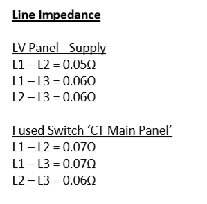
The current scanner is fed by a cable with line impedance 0.06 at source end of the sub panel that feeds it.


The new scanner must have a line impedance no more than 0.06 so basically I can't use the way on the current panel.


The client engineer has said to run from the intake and provide a cable calc to prove the line impedance is OK for the new scanner feed (this is D and B).


I am using AMTECH and was wondering if there was a way to output line impedance or if I need to show a calculation another way?


The client engaged a firm to do line impedance tests, and their report shows values measured between L1-L2, L2-L3 and L1-L3, but looks like they did testing at the sub panel and not at the intake.


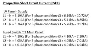
This is basically like PSCC right? So I can get PSCC from AMTECH, divide by root 3 and work out impedance from there?


Am I on the right track? Assistance would be much appreciated.


Regards


Anisur
Parents
  • Thanks for the reply davezawadi.


    The scanner doc says 150A fuses (AMTECH has no option for these, so guess will use a 160A in the model) - the numbers according to the manufacturer after a brief conversation was that the line impedance target is there because above that the CT image receives interference. Excerpts below:

    55111c761c7f1c322a26c5eea4854a1f-original-image.png
    2f42efcb3cc02908b05ff6a1deaea92f-original-image.png

    In terms of difference between measured values, between phases 2 have 0.06 and one has 0.05 at the source end of the existing panel.


    The client brief asks for new cabling to be derived from the building LV intake room and not from the supply Tx.


    Don't know if any relevance, but they have said:


    'It is to be noted that the CT scanner is to be used for non-invasive procedures as such no UPS/IPS is required for the scheme.' 


    So basically, I can call them up and ask about what if any margin their targets have - last thing we want is post completion getting blamed if there is interference on the image due to line impedance even if test results we do say it's OK.


    Are my thoughts on calculating line impedance on the right though do you reckon?

Reply
  • Thanks for the reply davezawadi.


    The scanner doc says 150A fuses (AMTECH has no option for these, so guess will use a 160A in the model) - the numbers according to the manufacturer after a brief conversation was that the line impedance target is there because above that the CT image receives interference. Excerpts below:

    55111c761c7f1c322a26c5eea4854a1f-original-image.png
    2f42efcb3cc02908b05ff6a1deaea92f-original-image.png

    In terms of difference between measured values, between phases 2 have 0.06 and one has 0.05 at the source end of the existing panel.


    The client brief asks for new cabling to be derived from the building LV intake room and not from the supply Tx.


    Don't know if any relevance, but they have said:


    'It is to be noted that the CT scanner is to be used for non-invasive procedures as such no UPS/IPS is required for the scheme.' 


    So basically, I can call them up and ask about what if any margin their targets have - last thing we want is post completion getting blamed if there is interference on the image due to line impedance even if test results we do say it's OK.


    Are my thoughts on calculating line impedance on the right though do you reckon?

Children
No Data