This discussion has been locked.
You can no longer post new replies to this discussion. If you have a question you can start a new discussion

Line impedance query

Hi 


I am looking at a job where a supply to a replacement CT scanner has to be calculated.


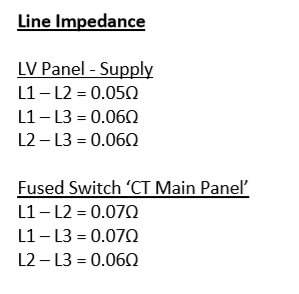
The current scanner is fed by a cable with line impedance 0.06 at source end of the sub panel that feeds it.


The new scanner must have a line impedance no more than 0.06 so basically I can't use the way on the current panel.


The client engineer has said to run from the intake and provide a cable calc to prove the line impedance is OK for the new scanner feed (this is D and B).


I am using AMTECH and was wondering if there was a way to output line impedance or if I need to show a calculation another way?


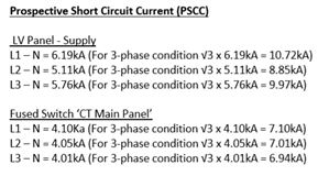
The client engaged a firm to do line impedance tests, and their report shows values measured between L1-L2, L2-L3 and L1-L3, but looks like they did testing at the sub panel and not at the intake.


This is basically like PSCC right? So I can get PSCC from AMTECH, divide by root 3 and work out impedance from there?


Am I on the right track? Assistance would be much appreciated.


Regards


Anisur
  • What CPDs are there in the scanner power supply? This number probably comes from these and a disconnection time in case of a fault, and this may not be the same as the GB numbers in BS7671, particularly if this is a US scanner. I suggest you contact the manufacturer and find out why this number is specified, as doing anything about it would be difficult and very expensive if you need a new cable from the supply TX just to meet the exact specification. You need to be aware that measured numbers which you have may not be very accurate, they could well be +- 20% with the average meter or even worse, at low values like this. How different are the measured values, one would expect very little difference between them, and again this measurement can be difficult depending on other loads connected to the supply? Refer to manufacturer (not a dealer or other intermediate as they will probably tell you anything) and get a written signed reply with a name in case of future problems with service contracts.
  • Thanks for the reply davezawadi.


    The scanner doc says 150A fuses (AMTECH has no option for these, so guess will use a 160A in the model) - the numbers according to the manufacturer after a brief conversation was that the line impedance target is there because above that the CT image receives interference. Excerpts below:

    55111c761c7f1c322a26c5eea4854a1f-original-image.png
    2f42efcb3cc02908b05ff6a1deaea92f-original-image.png

    In terms of difference between measured values, between phases 2 have 0.06 and one has 0.05 at the source end of the existing panel.


    The client brief asks for new cabling to be derived from the building LV intake room and not from the supply Tx.


    Don't know if any relevance, but they have said:


    'It is to be noted that the CT scanner is to be used for non-invasive procedures as such no UPS/IPS is required for the scheme.' 


    So basically, I can call them up and ask about what if any margin their targets have - last thing we want is post completion getting blamed if there is interference on the image due to line impedance even if test results we do say it's OK.


    Are my thoughts on calculating line impedance on the right though do you reckon?

  • I assume that this is the sort of CT machine that takes X-rays (rather than the magnetic kind of scanner, that used to be called nuclear magnetic resonance until folk got spooked by the idea that the atoms they are made of have nuclii  ?)

    The reason for checking is that the magnetic type require  cable layouts that keep the flow and return currents together.


    I'd be a bit wary of the claim of problems of interference, as this normally has more to do with cable routes and what else shares the supply, rather than the impedance per-se.

    Having said that,  in practice the current this machine draws will be quite bursty, so self interference where the voltage droops when it is time to take a picture may be an issue.)  Asking for a very low source impedance may just be a way of forcing installers to use a dedicated short fat cable.


    Line impedance is related to PSSC you are right,  - but note that for PSSC for fault survival without exploding the fuses, you are normally looking for the maximum of L-L or L-N or L-E fault states - normally L-L wins, but not always for all arrangements. Here the issue is the lowest current case, rather than the highest.

    Like Dave, I'd also be very wary of the accuracy of low value readings - a few milli-ohms is the sort or change you get with how well things are polished before they are bolted, and tests made with spiky probes are often just a fruit machine at that sort of level, and do not forget to include the impedance of the fuses themselves - a fuse that at 150A dissipates say 20-30 watts (not unusual for a BS88 style thing) is another milliohm or two, and you have very little margin.


  • Thanks mapj1 - they will get a dedicated fat cable, problem is that to meet their criteria it will be a 130m run. The client engineer did include that route in the tender, so OK in that sense, but still bit of a balancing act between safe margins and overdoing it size wise.


    I will grill the scanner people a bit more and try to come up with something sensible
  • Ok but I still think you need to speak to the manufacturers. Let us say you can get a supply with a 0.03 Ohm source, then you still need a cable giving let's say 0.02 Ohms for a 130m run corresponding to 0.15mV/A which gives a 300mm 4 core SWA. This is a 4-5x overdesign, of the 150A supply, but the supply may be around 80 kW during a scan, depending on the manufacturer. Where you can get a 0.03 Ohm supply is even more of a question which you need to work out. However this requirement seems very severe for a modern scanner with electronic power supplies, so back to my first point. You also need to check what the supply will be if from emergency generator power (which would be normal) as this is going to have to be a very large generator to get such a good supply. Fitting this cable in a building is a serious challenge due to its stiffness and minimum bend radius. Check my figures with Amtech. Good luck.
  • Former Community Member
    0 Former Community Member
    Computerized Tomography (CT) scans, combine a series of X-ray images taken from different angles around your body and uses computer processing to create cross-sectional images (slices) - so basically it's an x-ray set and line impedance is important.


    The scanner is a severely disturbing load when operating and the voltages can end up all over the place based on both voltage depressions and the extent of harmonic distortion caused by the load  - the load can also be quite impulsive.


    The short order solution mandated by most CT suppliers is to limit load impedance  - and to take Mike's comment above "a dedicated short, fat cable route" - if you are a long way from the transformers, then you need some pretty big cabling to limit the voltage bouncing around like tigger on acid


    One point about the "life safety" issues - I accept that diagnostics isn't a life safety issue in itself - if you can walk in you can walk out kind of thinking. However, many procedures in CT may well involve catheterization which is conductive - so they should be Medical Location Group 2 and should have medical IPS for shock risk. It is also pretty usual for the main equipment room to have small UPS support to manage shut down. It's entirely possible the designers may not have appreciated that fact


    Regards


    OMS
  • Thanks OMS and davezawadi for your replies, I have spoken to the manufacturer; guy I spoke to sort of said that the limit was hard and fast and then hinted that there might be some wiggle room as well which was confusing, but I.got a name for their technical top bod so I can involve them.


    Agree cabling will be nasty to install - maybe parallels or armoured singles might be an option for ease of install.


    Take your point OMS about maybe the IPS also - I will ask the question of the designers. Their spec did specifically state that not needed, but can't hurt to ask again.
  • Thanks OMS, that is useful to the OPer, I had not talked about the load characteristic, which is to take many short exposure Xrays as the scanner and tube rotate, going from zero to perhaps 70 kVA many times a second! Normal rotations are up to 2 revolutions per second depending on manufacturer and design, and 100 or more exposures per rev, so this is a fairly horrible load. It may be that the load is smoothed somewhat by electronic power supplies and large capacitors, but because the tube voltage is somewhere around 100kV the switching is not EHT but in the final voltage inverter. I would be most worried if this large fat cable was not all the way to the TX supply primary switchboard, as voltage fluctuations etc. would not be good for anything else. Anyway, more help from the manufacturer would be a good idea.


    Kind regards

    David
  • Somewhere around the few hundreds of metres it would become  cost-effective to move the HV and transformers nearer for any load that is that hostile - as an aside I have just calculated the following -

    You are asking for 150A per phase , and a droop of 9V at full load (150A* 0.06 ohms) - i.e. 3.8% voltage drop  (9/230 )

    A typical substation transformer droops 5% on full load, so you need a transformer rated for at least twice the load you are proposing to connect, to leave some voltage drop allowance for the cables.

    I am not familiar with modern designs, so there may well be subtelties I am not aware of, the last large X-ray rig I saw in pieces a good few years ago (15-20 years at least) used a klystron about the size and weight of my wife (but not the same form factor you will be pleased to realise) to switch the primary current into a pulse transformer that fired the actual Xray generator, and had more in common with a RADAR driver than any of the guys building it realised.

    I think as others said, you need the designers on-side.
  • I don't doubt for one minute the expertise of Mike, Dave, and OMS, but this all seems to be OTT. Just how are scanners put into a ship or a field hospital?