This discussion has been locked.
You can no longer post new replies to this discussion. If you have a question you can start a new discussion

Can Zs at DB ever be less than the Zs of the feeding circuit?

Former Community Member
I am reviewing an EICR recently issued for a building with several Distribution Boards feeding sub-Distribution Boards.

I have noted that in some instances, the figure recorded for 'Zs at this board' is significantly less than the Maximum Measured Zs for the circuit recorded on the feeding DB.

e.g. DB FF4 is recorded as being fed from DB FF1.  The feeding circuit to DB FF4 is recorded as having a Maximum measured Zs of 0.4 Ohm, but the 'Zs at this board' for FF4 is recorded as 0.05 Ohm - which is less than the 'Zs at this board' recorded for FF1 (0.08 Ohm) - and which, is in fact, in turn itself less than the 'Maximum measured Zs' for the circuit feeding it.  Can this be true or are there errors in the report?  I thought that cascaded Zs can only get larger due to the added impedance of the feeding circuits? This is not my primary area of expertise, but I am concerned that the EICR is being used to justify the upgrade of several circuits which have passed previous inspections with no problem (hope the resolution of the extracts from the EICR below are sufficient resolution to read)...

248ee514524cf5398885518b2007a96a-huge-image.png


b952bae4d3b1f32d959d675c6ede9a16-huge-image.png
05733e3016557d58306811936bac5e50-huge-image.png


Many thanks if anyone is able to confirm my concerns or otherwise put me straight...
Parents
  • Former Community Member
    0 Former Community Member
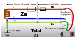
    Hmm - not so sure about that; R1 is always in series with the supply transformer.  Supplementary bonding can act to reduce the effect of R2 in the circuit, but R1 will always be there I think.  i.e. you can reduce the resistance/impedance of the return/earth path to the transformer, but the 'live' path in a fault condition is always going to be arriving via your live conductors.  So the total loop impedance is always going to be Ze (or Zs at source) + R1 + R2 (whatever R2 ends up being with the added benefit of supplementary bonding). I don't think you can ever reduce the total of R1 + R2 to below the value of R1 can you?

    b5f022b8c541fc43af08737196afc6be-original-image.png
Reply
  • Former Community Member
    0 Former Community Member
    Hmm - not so sure about that; R1 is always in series with the supply transformer.  Supplementary bonding can act to reduce the effect of R2 in the circuit, but R1 will always be there I think.  i.e. you can reduce the resistance/impedance of the return/earth path to the transformer, but the 'live' path in a fault condition is always going to be arriving via your live conductors.  So the total loop impedance is always going to be Ze (or Zs at source) + R1 + R2 (whatever R2 ends up being with the added benefit of supplementary bonding). I don't think you can ever reduce the total of R1 + R2 to below the value of R1 can you?

    b5f022b8c541fc43af08737196afc6be-original-image.png
Children
No Data