The IET is carrying out some important updates between 17-30 April and all of our websites will be view only. For more information, read this Announcement

This discussion is locked.
You cannot post a reply to this discussion. If you have a question start a new discussion

Can Zs at DB ever be less than the Zs of the feeding circuit?

Former Community Member
I am reviewing an EICR recently issued for a building with several Distribution Boards feeding sub-Distribution Boards.

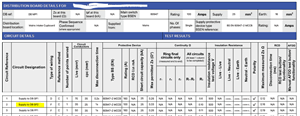
I have noted that in some instances, the figure recorded for 'Zs at this board' is significantly less than the Maximum Measured Zs for the circuit recorded on the feeding DB.

e.g. DB FF4 is recorded as being fed from DB FF1.  The feeding circuit to DB FF4 is recorded as having a Maximum measured Zs of 0.4 Ohm, but the 'Zs at this board' for FF4 is recorded as 0.05 Ohm - which is less than the 'Zs at this board' recorded for FF1 (0.08 Ohm) - and which, is in fact, in turn itself less than the 'Maximum measured Zs' for the circuit feeding it.  Can this be true or are there errors in the report?  I thought that cascaded Zs can only get larger due to the added impedance of the feeding circuits? This is not my primary area of expertise, but I am concerned that the EICR is being used to justify the upgrade of several circuits which have passed previous inspections with no problem (hope the resolution of the extracts from the EICR below are sufficient resolution to read)...

248ee514524cf5398885518b2007a96a-huge-image.png


b952bae4d3b1f32d959d675c6ede9a16-huge-image.png
05733e3016557d58306811936bac5e50-huge-image.png


Many thanks if anyone is able to confirm my concerns or otherwise put me straight...
  • Were the measurements taken with all loads disconnected? Loads switching in and out can affect results.


    I could also foresee theoretical situations in sprawling buildings, where what's locally bonded provides a low impedance earth path back to the MET, but perhaps not to that extent?


    Of course, without knowing anything about this particular installation, I would certainly be asking the question you are asking.
  • Would expect mainswitch of tested DB to be off? Likely two differing inspectors per DB. Blurred image gives no clear detail, BUT, looks like R2 and Zs recorded on distn circuit to DB. Odd for EICR. Perhaps this Zs calculated, erroneously, simply from a wander lead origin to DB [R2], then inspector of sub db did live Zs test.


    edit to add:  Mixed disconnection times one DB to the other.
  • but I am concerned that the EICR is being used to justify the upgrade of several circuits


    But is there any observation for that dist'n circuit recorded suggesting "upgrade" ?


    That will indicate if it was just a clerical error or not.
  • In a steel framed building you might get this, as in effect the later disboard, connected to the metal building frame, is better grounded than the board that supplies it if that one is say on a brick wall. However, that is not a common situation.


    But, are any of the distribution circuits Zs so bad that a 5s disconnection would fail, and are any of the final circuits so bad as to fail 0.4 seconds - if not then it is nothing more than a comment. What 'upgrades' are being proposed, and why? -  it may be sensible - it may be just making work.


  • Former Community Member
    0 Former Community Member
    Many thanks for everyone's responses to date on this.

    I do not know what they did regarding disconnecting loads etc when they did their tests.  This was actually a medium-size 2-storey church building built over 100 years ago, so not, for example, sprawling over a multi-building site, but has had various extensions and modifications over the years, so may have some structural steel members here and there.  The inspector has acknowledged multiple errors in the report elsewhere, but I was checking if these Zs values were also a bit of a red flag.  There is concern over one particular area of work that he has recommended, which is to replace/upgrade a circuit for reasons that the EICR does not support (a circuit which the inspector says in his observations is only protected by a 32A fuse, but which the EICR clearly says is protected by a 100A fuse). When pushed for clarity, he is now saying 'ah well, that circuit is actually fed from another circuit which is mislabelled'. The whole thing is just a bit fishy, but I am not sure whether to call him out on it or not.  He may be telling the truth, but the EICR (marked unsatisfactory) that he has issued seems to be full of factual/typo errors and I just cannot see that it clearly supports the conclusion that there is a circuit that need upgrading.  If you take the report at face value, as written, it is claiming that connections/circuits exist that just do not exist on the report and which were not recorded on the last inspection report 5 years ago by a different inspector/company. Either his report has failed to record the bad circuits that do exist, or he is recommending to replace circuits that the EICR does not indicate need replacing/upgrading.  On many of the circuits on the EICR, the 'Maximum measured Zs' for an individual circuit bears no resemblance at all to the 'Zs at this board' + the measured R2 for the circuit.
  • Former Community Member
    0 Former Community Member
    In the FF1 for example, the 'Zs at this board' is recorded as 0.08 Ohm.

    Circuit 1/L1 records 'Continuity R2' as being 0.1 Ohm.

    'Maximum measured Zs' for this circuit is recorded as 0.04 Ohm - less than the R2 for the circuit itself. Can this happen? 


    Circuit 3/L3 has a 'Continuity R2' recorded of 0(?), or 'R1 + R2' of 0.01, and yet a 'Maximum measured Zs' of 0.4 Ohm. I would have expected the measured Zs to be very close to 'Zs this board' + R2. (neglecting the fact that he has managed to find an impedance-less conductor linking two Distribution Boards.
  • If you can provide the following it may help someone give a more specific answer

    1: Is there a steeple?

    2: What is declared method of earthing... TT or a TN?

    3: Protective bonding conductors to what, eg  Steel, LPS, gas water.


    It all seems fairly self contained....but is the Origin/ metering actually inside this building?
  • Former Community Member
    0 Former Community Member
    1. No 'steeple', but there is a 'tower'.  Interested to know how that affects matters (I mean that genuinely - it's not intended to be a provocative question :-)

    It has not had any floors 'added' on top, but it did have an internal floor 'inserted' in the middle some 10 years ago, and that would have required considerable new wiring added at the time plus, I would guess, numerous structural steel support beams.
    c7b22a4cfeddc7224510226caf07a88a-original-image.png


    2. TNC-C-S is declared on the EICR;
    f72db1afc387566baa3d504d18b41a23-original-image.png


    3. You will see from the above that 'N/A' has been recorded for all Main Bonding.


    4. It is a self-contained building, and I believe the meters are all contained within the building.


    My main concern is regarding feeder circuits to DB GF2.(not my original question, but the reason for my trying to check other details on the report);

    The EICR records as follows;

    DB GF2 is supplied from 'DB MP1 Circuit No 2TP' via a 25mm^2 live conductor, 16mm^2 earth and MCCB rating 160A;
    eb38f6c43bfb7e54b4de5cfff36023ad-original-image.png


    DB MP1 circuit 2 records that GF2 is fed by 100A MCCB via 35mm^2 live conductor and 25mm^2 cpc;
    ab9c9b36e3ff83019589193442b64be7-original-image.png


    and his observations in the EICR state;
    8dff8333e6ed8b36fb3730fe04710d22-original-image.png

    and he has quoted to 'To supply and install new 25mm 3 Core Armoured cable from Main Electrical intake to

    Distribution Board GF2. Disconnect and cut out where possible redundant feed to GF2'.


    On being challenged that he has got his GF2's and GF3's mixed up, and what he says in his conclusions does not match what is recorded in his EICR, the inspecting contractor (who issued the EICR) is then saying;

    "Sorry there was an error on my observations.
     
    GF2 is fed from MP1 not GF1.
     
    GF2 is labelled in MP1 as “Boiler Panel” but it feeds GF2 which the feeds Boiler Panel.
     
    This is on a 32a MCB. GF3 is fed from a 62a MCB in GF2.
     
    We  are not in the business of making recommendations for cables that are not necessary, our proposal is to give you a safe and fully compliant electrical installation.
     
    Please confirm you still wish us to continue with these works."


    This still does not match what his EICR says, raises all sorts of questions regarding how accurate the EICR is, and whether it is safe to rely on what he is recommending.  I am thinking his EICR is just too scrambled and full of inconsistencies to be taken as credible.

    Or am I missing something?


    Many thanks for your interest - it is much appreciated.


  • Former Community Member
    0 Former Community Member
    Originally posted by “Peter S3:

    (hope the resolution of the extracts from the EICR below are sufficient resolution “


    Hi Peter welcome to the forum :) Not your fault but those pics are making my eyes hurt, how did you upload them? Pictures that appear blurry could be previously clicked on and viewed in more detail, I am not sure if this has changed recently.
  • Peter S3:

    I am thinking his EICR is just too scrambled and full of inconsistencies to be taken as credible.

    Or am I missing something?


    I cannot read your original charts, but there seem to be some basic errors in the later ones. Sections I and J: nominal voltage and frequency appear to be measured. If Ze = 0.14 Ω then at 243 V the PEFC is around 1.717 kA, but matey seems to have forgotten the possibility of a L-L fault. Why has supply polarity not been checked? The size of the MPBC is not given and there is no indication as to what is bonded.