This discussion has been locked.
You can no longer post new replies to this discussion. If you have a question you can start a new discussion

Can Zs at DB ever be less than the Zs of the feeding circuit?

Former Community Member
I am reviewing an EICR recently issued for a building with several Distribution Boards feeding sub-Distribution Boards.

I have noted that in some instances, the figure recorded for 'Zs at this board' is significantly less than the Maximum Measured Zs for the circuit recorded on the feeding DB.

e.g. DB FF4 is recorded as being fed from DB FF1.  The feeding circuit to DB FF4 is recorded as having a Maximum measured Zs of 0.4 Ohm, but the 'Zs at this board' for FF4 is recorded as 0.05 Ohm - which is less than the 'Zs at this board' recorded for FF1 (0.08 Ohm) - and which, is in fact, in turn itself less than the 'Maximum measured Zs' for the circuit feeding it.  Can this be true or are there errors in the report?  I thought that cascaded Zs can only get larger due to the added impedance of the feeding circuits? This is not my primary area of expertise, but I am concerned that the EICR is being used to justify the upgrade of several circuits which have passed previous inspections with no problem (hope the resolution of the extracts from the EICR below are sufficient resolution to read)...

248ee514524cf5398885518b2007a96a-huge-image.png


b952bae4d3b1f32d959d675c6ede9a16-huge-image.png
05733e3016557d58306811936bac5e50-huge-image.png


Many thanks if anyone is able to confirm my concerns or otherwise put me straight...
Parents
  • Former Community Member
    0 Former Community Member
    I've made the 2015 and 2020 reports available for viewing again - I think you will find them back under their original posts.

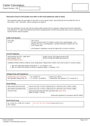
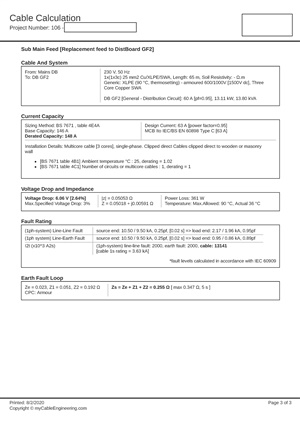
    Also, please see below latest attempt to justify their quote to install a new cable feed to DB GF2, after I pointed out that we had proven that DB GF2 was fed by a 3-phase 100A MCCB and not a 1-phase 32A MCCB;

    I will be interested to see if you come to the same conclusion on their cable calcs as I did;


    "Yes, sorry you are correct on the routing of the feed to GF3. Unfortunately there was some confusion at our end regarding “feed to Boiler Room” and assuming this was the feed to GF2.
     
    However although this means that there is not a MCB Discrimination issue, there is still the problem that way GF3 is fed, results in excessive voltage drops on full load and the Disconnection tomes of the RCBO FAILS test.
     
    Attached is our cable sizing report based on feeding GF3 the way it is currently fed. As you can see it FAILS on all three calculated headings.
     
    Based on this our recommendation to run a new feed direct from MF1 to GF3 stands as this is the only way the required disconnection times and impedances can be achieved. It will also overcome the potential full load Voltage Drop issue.
     
    Please digest the attached report."


    c7254864528d624b742fa01b38afb8d1-original-cable-calculation_page_1.jpg

    (pages 2 details a different circuit not part of this issue).


    Page 3 (below) details their proposed new circuit to GF2;
    f6cbd3a6b81ac799e790812568ce98c9-original-cable-calculation_page_3.jpg
Reply
  • Former Community Member
    0 Former Community Member
    I've made the 2015 and 2020 reports available for viewing again - I think you will find them back under their original posts.

    Also, please see below latest attempt to justify their quote to install a new cable feed to DB GF2, after I pointed out that we had proven that DB GF2 was fed by a 3-phase 100A MCCB and not a 1-phase 32A MCCB;

    I will be interested to see if you come to the same conclusion on their cable calcs as I did;


    "Yes, sorry you are correct on the routing of the feed to GF3. Unfortunately there was some confusion at our end regarding “feed to Boiler Room” and assuming this was the feed to GF2.
     
    However although this means that there is not a MCB Discrimination issue, there is still the problem that way GF3 is fed, results in excessive voltage drops on full load and the Disconnection tomes of the RCBO FAILS test.
     
    Attached is our cable sizing report based on feeding GF3 the way it is currently fed. As you can see it FAILS on all three calculated headings.
     
    Based on this our recommendation to run a new feed direct from MF1 to GF3 stands as this is the only way the required disconnection times and impedances can be achieved. It will also overcome the potential full load Voltage Drop issue.
     
    Please digest the attached report."


    c7254864528d624b742fa01b38afb8d1-original-cable-calculation_page_1.jpg

    (pages 2 details a different circuit not part of this issue).


    Page 3 (below) details their proposed new circuit to GF2;
    f6cbd3a6b81ac799e790812568ce98c9-original-cable-calculation_page_3.jpg
Children
No Data