This discussion has been locked.
You can no longer post new replies to this discussion. If you have a question you can start a new discussion

Zs, to test or calculate?

A large contractor working on our site have told me yesterday that it is their policy not to live test final circuits where they cannot use a plug? In order to reduce risk, they will now only calculate Zs, on circuits where they would have to open an enclosure, such as FCU's and light fittings.
The control measures we insist are in place, are IP2X equipment, GS38 leads, two man rule with second man having resus training, among others. So I feel the risk has been reduced to as low as reasonably practicable. An d my instinct tells me that a measured Zs reading must be more accurate than a calculated one, since it will include all parallel paths under test.
The contractor is happy to live test distribution circuits, so it seems they want to pick and choose.
They also state that this is how things are now, and have worked at many different sites, Cross Rail, Heathrow, various MOD sites etc, and that they al accept this as common practice.

I like some opinions to find out what's going on out there on other sites. 
  • Sparkingchip:

    With many light fittings now being LED without a removable lamp you cannot even fall back on some of the aids to safe working.


    See the source image


    So for the EICR you need to confirm the polarity at the fitting, single pole switches and breakers are in the live phase, loop impedance and possibly the RCD trip time. 


    Is opening the ceiling rose of a pendant, which does not require any tools to test anymore dangerous than removing the cover of the consumer unit to test Ze, etc?


    Andy B


  • From experience I would say two people on a circuit is more dangerous than one, I have seen other electricians working in pairs energise circuits whilst one of them is still working on it, one pair did it three times in one day.


    Andy B
  • davezawadi (David Stone):

    Well Graham, perhaps you have hit the nail on the head. I like to do testing with 2 people with radio communications, it is very much quicker, and overcomes your idea that an open accessory or whatever left with a meter and perhaps a warning notice is dangerous to anyone. The idea that one man tests a large installation by walking miles each day is simply arcane.

    Hang on ... you mentioned the isolate ... connect ... renergize process?

    We are in the 21st-century and need to use 21st-century tools. R1 + R2 testing takes very little time, insulation testing has someone close to the items being tested etc. You can see how this is so much safer and quicker but want to give a method statement and procedure which removes the value of the work.

    Even with 2 people, it's still unfortunately a "process" or "method" vs "safety". As I said, it's not a matter of changing "what the electrician thinks is best" on these sites, but convincing the H&S Team - who might well be held at least partly to account if the maintenance checks on their electrical systems were deemed inadequate, so I guess after all it's their call.

    So be it, but I hope there is never a problem due to inadequate testing, it is likely one day. Personally I have no problem with live testing at all, but then I am of that age.

    So, you mentioned 21st century.


    I have a feeling that we are at a point where loop testing and prospective fault current testing might be a thing of the past ... because microgeneration with inverter output can provide a totally erroneous and meaningless reading.
  • Well Graham, perhaps you have hit the nail on the head. I like to do testing with 2 people with radio communications, it is very much quicker, and overcomes your idea that an open accessory or whatever left with a meter and perhaps a warning notice is dangerous to anyone. The idea that one man tests a large installation by walking miles each day is simply arcane. We are in the 21st-century and need to use 21st-century tools. R1 + R2 testing takes very little time, insulation testing has someone close to the items being tested etc. You can see how this is so much safer and quicker but want to give a method statement and procedure which removes the value of the work. So be it, but I hope there is never a problem due to inadequate testing, it is likely one day. Personally I have no problem with live testing at all, but then I am of that age.
  • With many light fittings now being LED without a removable lamp you cannot even fall back on some of the aids to safe working.


    See the source image
  • No one has said that electricians are not competent, and I'm not trying to insinuate that.


    The argument used is simply based on the hierarchy of control for safety management, and nothing else.


    From experience (on some of these sites), I would say the arguments presented by Mike and David would not demonstrate that carrying out the loop impedance testing on every final circuit would provides a sufficient increase in safety to permit the electrical inspector to be exposed to the hazards of carrying out loop tests at IP2X terminals when an alternative method might be available.


    Unfortunately, David's method would leave exposed live IP2X terminals accessible in the period between re-energizing and returning to take the reading. There would need to be a means of control to prevent that access. In any case, you have to follow a method. If the measurement is being carried out at the point of isolation, you have that control, provided you follow the method.


    I've italicised method because the health & safety managers and their health & safety advisors would call this an administrative control in the hierarchy of controls. The hierarchy of controls is considered to be the following list, most effective at the top, least effective at the bottom;
    1. Eliminate the hazard

    • Substitute the hazard

    • Engineering controls protective devices, interlocks, guards, etc. - effectively, separate people from the hazard

    • Administrative controls changing the method of work to avoid hazards and/or reduce the severity

    • Use PPE


    For this reason, putting in place administrative controls (safe method of work) is seen to be trumped hands down by Eliminate and Substitute.


    So, and electrician on one of those sites has an uphill battle to get loop testing on all final circuits permitted.
  • This pdf (archived:pdf) is an effort to explain in more detail why |Z| is not what's measured — and so short-circuit current estimates can be grossly wrong — when working only with voltage magnitudes, light resistive test-load, and reactive source.  Due to the situations in which a source has high X/R, I do not see this as a particularly practical issue (?).  I simply mention it as a possible interest.  The crux is the following relation, where Rt is the test-load and the other parts are in the Thevenin-model of a linear ac source:

    3dbee84fef5c6f95bcb990f2661ead52-original-zest_isc.png


    Regarding capacitors and RCDs .. the probable first objection would be "what if someone touches one end of a capacitor with wet hands?" (with its other end connecting to a phase-conductor).  In a situation with low body resistance, one could get a dangerous current even with a series capacitive reactance of serveral times the body resistance, so the total would look very close to a capacitor.  Perhaps the capacitive current could be a reason to delay a little more but still within the required operating time. 

  • I think I am with DZ, an electrician who cannot do live testing "for safety reasons"  is being unnecessarily  limited, and is likely to miss a whole slew of faults that are only obvious after re-assembly, and may actually be faults that are introduced by disconnecting things to do the -dead tests.


    At the risk of tracking off a bit,  in the tester  there are 2 test states, a near open circuit and the test resistor . If it only looks at the voltage i nthe 2 states  I agree you measure |Z| i.e.   the modulus of the impedance, and are unsure o how much f it is real or imaginary.

    You need another piece of information to separate that, and traditionally it is to connect an L or C and remeasure  but if you can count the cycle periods and and the small phase shifts between the load on and load off cases then you can say something.  (and a modern microprocessor clocked at MHz can measure short times)

    The simple instruments do not. as all you need is the fault current, and that is driven by |Z| . But it is in principle possible to sort out R from X, so long as they are comparable.


    IT would be possible to make an RCD that looked at the phase of the imbalance current against the voltage and could distinguish capacitors from a human, but so far no-one seems to think it is worth doing.
  • I am not at all sure that this policy is in any way satisfactory. If a qualified electrician cannot safely test any part of a live circuit he is inadequately qualified for the testing job. This is simply a time saving idea, which may well deteriorate to no testing at all, because it is quicker. The proper completely safe procedure is as follows:


    Isolate the circuit. Connect your loop tester using suitable connectors clips or insert the leads into the connector, accessory or whatever live terminal and the other to earth. Energise the circuit. Test Zs and note the reading. Reverse the procedure to disconnect. If anyone can see how this is unsafe I should love to hear.


    You will never find faults by calculation. It is faults we are looking for, loose connections to earth conductors where the sleeving is trapped under the screw etc. One never knows the quality of the workmanship and such are common faults in new installations! Why calculate (presumably that is already done in the design) when a proper test is much better and will find real faults. Multiple paths cover up these faults and ARE NOT SAFE.


  • That's true (lyledunn).  A method that compares voltage magnitudes with and without a resistive load (where that load impedance is many times the source impedance, e.g. to take 20 A) is very insensitive to reactance in the source - it practically doesn't see it at all. 


    One can make inferences based on curve fitting for a range of resistive loads, but that's more for amusement than practical ... I've tried it a few times. 


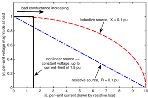
    The following plot was my attempt some years ago to illustrate the relation between current and voltage when a varied resistive load (conductance increasing from open-circuit to short-circuit) is connected to a source with either purely resistive (blue) or purely reactive (red) impedance, or to a current-limited power-electronic source.

    - With the resistive source and load the gradient is a nice straight line as with dc circuits, so any measurement that varies the load between (say) zero and 20 A in a system with 1 kA short-circuit current would make a good estimate of the short-circuit current. 

    - But with the reactive source and resistive load the estimate based on this same pair of currents would be a much higher short circuit current than the actual value that's been chosen here to be the same as in the resistive case, because the voltage drop due to mainly resistive current flowing through the reactive source impedance is pretty well in quadrature with the larger source voltage, just as you say. 

    - (And on the other hand, the current-limited inverter could regulate its voltage to look very stiff, and yet provide much lower short-circuit current: it is 'brittle' stiffness!)

    fd25a70f5dda7bc808aecf8919fccae9-original-vi.png


    "In theory", using phasor calculation, one could calculate the source impedance easily for a Thevenin-style source with resistive and/or reactive impedance. But that would require knowing the angle relation between the voltage phasors at the source (assumed constant for the 0 A and 20 A case) and at the measurement point. The simple practical measurements don't have a way to know this, and just measure voltage magnitude. It is possible with analog methods (phase-locked loop) or digital methods (extrapolate a sine-wave for further cycles) to keep a memory of the phase of the source-voltage based on the times when the current isn't being drawn, and to assume this value continues in the few cycles afterwards when the test-current is being drawn. Then one should be able to get a better calculation, although the small change in voltage for a resistive perturbation of a reactive system would still make it more susceptible to noise. Using a test-inductor (or capacitor) as the load instead of a resistor would let the source reactance be measured while largely ignoring the source resistance. Or electronics could synthesise the currents in phase and quadrature. 

    Getting away from phasors, one can take rapid pulses of current such that much of the voltage drop is caused by L*di/dt instead of R*i, as a way to assess inductance (but this is rather dependent on local shunt capacitance). 


    There's a lot that can be done. Some has been in other applications of impedance estimation, such as inverters that use reactive power consumption to avoid excessive voltage rise with active power injection, or distance-relays that look at the L*di/dt rather than phasors.  Installation testers have got cleverer and more digital, but I'm not sure about the current state of art in implementations by the usual manufacturers of today's products.  They tend not to say anything very interesting about the fine details!  One has to test the tester.  


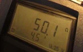
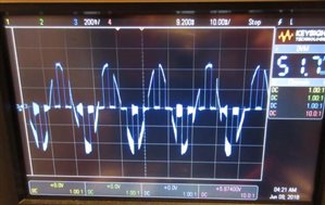
    I don't remember the details of the setup, but the following are from a quick check a few years ago, using an oscilloscope to see what a simple MFT was doing during (I think) a low-current (RCD-friendly) loop test.  It correctly measured the oscilloscope's supposed input resistance, and the oscilloscope showed an interesting waveform that definitely wasn't sinusoidal. 
    593e6f29ddf3a90425f51a19538b83da-original-zest_osc.jpg  35759f8b710f1e4602108c025a5d9f43-original-zest_result.jpg