This discussion has been locked.
You can no longer post new replies to this discussion. If you have a question you can start a new discussion

Theoretically optimal location of a distribution substation

Former Community Member
Hello, 
I have the following problem with the preliminary design stage of a residential area:

The software I use can calculate a theoretically optimal location of a distribution substation for low-voltage networks. This place is calculated as a "center of power demand" or "center of gravity" of electrical consumers.

If the substation locates in this optimal place, we can design 0.4kV distribution feeders with a minimum length and power losses in low-voltage feeders are minimal. 

I understand it’s almost impossible to put it exactly there, and I consider some sites nearby. But the architect believes that this is unacceptable in terms of landscape design and wants to place the substation in a far corner.

Who should be the arbiter in this situation?  DNO representative takes a neutral position.  Local authorities are completely on architect side, they do not care that long power cables will heat the atmosphere for many years to come.
3602925e57eac86d03447a5e59fc8e9b-huge-image.png
  • Former Community Member
    0 Former Community Member
    Well, to follow an optimum design, you would be losing a dwelling - which usually has significant monetary value, so you can understand why the architect working for the developer wants the substation on the least valuable bit of land on the plot.


    Money talks, so you wont win this one, however:


    1 - From your design, why are you feeding every plot individually with each cable going back to the sub - you'll need a fuse rack of epic proportions (which costs money)


    2 - You can always mitigate the I2R losses with a slightly bigger cable - which is cheap compared to the trench costs


    Personally speaking, put in a few 3 phase feeders from the substation and "T"off for each property - two or 3 circuits would deal with the whole lot at minimal cost and optimum size to mitigate the I2R loss. Essentially let the DNO put in the sub, then get an IDNO to wire up the utility on site to each dwelling.


    What is your estate street lighting strategy ?


    Regards


    OMS


  • Hi Alex

    I see that you are considering this in a non-UK country from the 10kV/400V substation. Is it usual to supply all 3 phases to each property, and what is the estimated diversity applied loading per house? If we worked with typical UK numbers and a single phase each, the supply cable would be fused at 400A and about 2kVA per house assumed. That would be about 100 houses on a cable, but as loads are rising one should consider more per house, with EV charging perhaps 4 or 5 kVA. Even so your site would work with only one cable to all properties, and if you are willing to fit 2 or 3, you should have a very safe design with 26 properties total, and perhaps a 500 kVA transformer. This would allow for expansion on surrounding land or further consumption by this development. OMS is quite right, the civils and jointing cost will be much more than the cable, so it is not worthwhile to comprimise cable costs.
  • It is usual practice to run the cables along the sides of the roads rather than crossing land that may become other people’s property requiring lots of legal work writing wayleaves.


    Sometime in the UK it is virtually impossible to avoid crossing other people’s land as many housing estates are built with shared driveways. The water company sells an insurance to cover your private supply pipe, most people don’t bother paying for it, but as one guy said “When three of your neighbours drives have to be dug up and relayed in addition to your own if the pipework needs replacing, the insurance premium doesn’t seem to be so expensive “.
  • Former Community Member
    0 Former Community Member
    OMS:


    Personally speaking, put in a few 3 phase feeders from the substation and "T"off for each property - two or 3 circuits would deal with the whole lot at minimal cost and optimum size to mitigate the I2R loss. 

    Power supply is designed on the basis of several 3-phase loop-feeders (underground) from the substation. If we compare the lengths of these loops for both variants, they any way will be much shorter in the variant with an optimal location of the substation.

    Street lighting (including a small park and a playground) will be designed by separate lines from a separate cabinet near the substation
  • Former Community Member
    0 Former Community Member
    davezawadi (David Stone):

    Hi Alex    I see that you are considering this in a non-UK country from the 10kV/400V substation. 


    Yes, we are doing this project in one of the EU countries. This is a real project, but I would like to consider the situation as hypothetical.

    OMS is quite right, the civils and jointing cost will be much more than the cable, so it is not worthwhile to comprimise cable costs.

    I wanted to compare the cost of electricity losses in low-voltage feeders but not the cost of cables. Over 30-40 years of operation there will be a large amount of costs for power losses.  Of course, the end consumer pays for everything. But if the DNO would get shorter cables with less power losses, then they could take the saved money to himself.


  • The simplest way of reducing cable losses is often to use larger cable, rather than a complex layout that may introduce other costs.

    In most cases cables should be under the footpath beside a public road, avoiding the costs and complications of wayleaves will more than pay for larger cables.

    Doubling the cable size will less than double the cable cost, and the trench will cost the same.


    Loop mains that are fed from each end will reduce losses, and may permit of feeding from one end only during faults.


    Also it may be more economic to locate the substation near an EXISTING HV circuit, preferably a ring circuit, rather than to install significant HV cable.
  • Former Community Member
    0 Former Community Member
    Alex

    I wanted to compare the cost of electricity losses in low-voltage feeders but not the cost of cables. Over 30-40 years of operation there will be a large amount of costs for power losses.  Of course, the end consumer pays for everything. But if the DNO would get shorter cables with less power losses, then they could take the saved money to himself.


    You cant evaluate cost without looking at cable size though - even in your theoretical optimum layout, a larger cable (ie more expensive) will consume less power.


    It's an economic balance - will the increased cable size pay for itself in a given period (accounting for interest on money etc etc)


    Regards


    OMS


  • Former Community Member
    0 Former Community Member
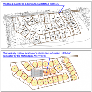
    Dear colleagues, sorry. I finally understood where the misunderstanding came from.  I had to make the right explanations for the pictures.

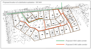
    There are no overhead lines and no single feeders on the plan above. There are no overhead lines in this project.

    The picture above shows the result of the MeteorSPEC's work - the cartogram of consumers (circle area is proportional to power demand) and the procedure of determination of theoretically optimal location of a substation.

    Currently designed cable routes are located as follows:
    0f4abc065c1e559ed8725a6d23abbcf1-original-image.png

  • I cannot comment technically, but what I would say is that substations are not a blight on the landscape. My local one is two houses away and open air. I think that I know where they all are locally, but some have been difficult to spot - behind fences just like gardens. In a new development (now two years old) they are in small brick buildings which look like small garages.


    The gas equivalent used to be underground, but now lives in a hut. It has been concealed by shrubs.


    Any decent architect should be capable of making a substation aesthetically acceptable.


    Who should be the arbiter must be a matter of local law, but I support Alex's position.
  • I think that the biggest loss is likely to be the transformer, and selecting the lowest loss type would probably be worthwhile. 2% of 500 kVA is a lot of power, and particularly the unloaded loss needs to minimised. Whilst transformer losses appear small at first view, they are significant overall in the bigger picture. Full load efficiencies are only part of the story, and the cooling fins, radiators, etc. describe the real power loss to be expected. Better core materials and design have a big impact on real power loss, although this may be 1% of the full load rating, it is a lot of money over a 50 year or more life.