This discussion has been locked.
You can no longer post new replies to this discussion. If you have a question you can start a new discussion

Theoretically optimal location of a distribution substation

Former Community Member
Hello, 
I have the following problem with the preliminary design stage of a residential area:

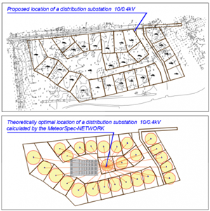
The software I use can calculate a theoretically optimal location of a distribution substation for low-voltage networks. This place is calculated as a "center of power demand" or "center of gravity" of electrical consumers.

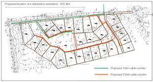
If the substation locates in this optimal place, we can design 0.4kV distribution feeders with a minimum length and power losses in low-voltage feeders are minimal. 

I understand it’s almost impossible to put it exactly there, and I consider some sites nearby. But the architect believes that this is unacceptable in terms of landscape design and wants to place the substation in a far corner.

Who should be the arbiter in this situation?  DNO representative takes a neutral position.  Local authorities are completely on architect side, they do not care that long power cables will heat the atmosphere for many years to come.

3602925e57eac86d03447a5e59fc8e9b-huge-image.png
  • Former Community Member
    0 Former Community Member
    Alex Juhanson:
    Dear colleagues, sorry. I finally understood where the misunderstanding came from.  I had to make the right explanations for the pictures.

    There are no overhead lines and no single feeders on the plan above. There are no overhead lines in this project.

    The picture above shows the result of the MeteorSPEC's work - the cartogram of consumers (circle area is proportional to power demand) and the procedure of determination of theoretically optimal location of a substation.

    Currently designed cable routes are located as follows:
    0f4abc065c1e559ed8725a6d23abbcf1-original-image.png


    OK - understood


    The architect location does seem to optimize the cable costs on the HV installation, and a bit of fiddling with the LV feeders wouldn't go amiss. It also seems to allow direct DNO access from the feeder road and clearly the aesthetic is considered as improved.


    Have you actually worked out the differences in LV cabling losses for both options and then included the reduction in HV costs. Just by observation, there would seem to be 4/5ths of the square root of not very much difference (particularly when you take on board the point about transformer losses dominating)


    Regards


    OMS


  • IIRC most of the LV network losses end up attributable to the service cables from the LV mains to the houses. This on the basis that losses are I squared so the relatively fewer moments where the service cables are highly loaded tend to dominate.  A bit counter intuitive I know.  I think there was a study by somebody at Imperial College into this.  That would argue for shorter, larger service cables to reduce losses.
  • You really do need to think carefully about this. Yes, bigger cables reduce losses, as do shorter ones. However, these losses only occur in relation to loading. Unfortunately, this only applies to some of the transformer losses, which occur continuously at zero load. The jointing cost of service to main cables also increases with size, particularly if you use aluminum cables. What is your design voltage drop, and how often do you expect this to occur? This is the point which you are missing, maximum demand is not a continuous thing with housing, it occurs for fairly short periods, and at predictable times. Cables are best designed appropriately, considering all factors including the thermal time constants to get the most cost-effective design over the whole lifespan (100 years?).
  • Former Community Member
    0 Former Community Member
    Thanks to all. Yes, choosing a substation location is a complex task. We must consider many factors - technical and non-technical.

    OMS listed in his posts the main non-technical factors - the price of land, the convenience of access and maintenance, nearness to existing HV-lines.

    If we talk about the technical part, then the optimization problem is divided into two components:

    1. How to reduce the length of cable lines and thereby reduce losses in the lines;

    2. How to find cost-effective cable cross-sections. This is a balance between the cost of investment and the cost of losses over a lifetime - this can help Kelvin’s law. Some information you can find on   www.electricaleasy.com/.../economic-choice-of-conductor-size-kelvins-law.html

    The problem is that at the stage of the preliminary project, we define only the corridors for communications and internal estate borders. Power demands of consumers have so far been determined tentatively. These are individual residential buildings of 2-3 floors. Heating is gas. Cables will be selected and designed in the next stages. With a high degree of probability underground Al 4x240mm2 will be used.

    At this preliminary stage of the project, we can make only one type of optimization – to find a place for the substation to reduce the total length of 0.4 kV distribution cables.

    I will write a little later about the calculation of losses
  • Former Community Member
    0 Former Community Member
    Alex Juhanson:
    These are individual residential buildings of 2-3 floors. Heating is gas. Cables will be selected and designed in the next stages. With a high degree of probability underground Al 4x240mm2 will be used.


    Are you sure ? - given you only have circa 9 properties per phase, and gas heated buildings, I would have thought the feeders would be much smaller than 240mm2  - even in aluminium.


    Assuming for such a small number of houses, you aren't planning any backfeeds from other systems or between systems, then typically feeders would be 185mm2 with service cables being 25mm2 (single phase)


    185mm2 is usually selected over 95mm2, as it provides for future flexibility - if you really need more than a 185mm2, then the next "optimum" size would be 300mm2


    Regards


    OMS


  • Former Community Member
    0 Former Community Member
    OMS:

    Are you sure ? - given you only have circa 9 properties per phase, and gas heated buildings, I would have thought the feeders would be much smaller than 240mm2  - even in aluminium.


    Hi, OMS

    Of course, I'm not sure.  As I wrote earlier there are plans to build big houses of 2-3 floors. The main fuse calculator we use gets the following results for residential buildings in the projected area:


    Type of place of consumption:  Detached house
    Area:  200 m2
    Loads: Electric sauna heater + Oven + Electric stove + Washing machine + Dishwasher + Other kitchen appliances + Other household appliances + Lighting + Home electronics + Air conditioning + Garage appliances + Outdoor appliances.

    Number of phases: 3
    Suggested main fuse rating:  3x32A

    Amperage of the main fuse is calculated is a recommended value, the calculator considers the consumption habits of an average household.  Some houses may have pools. May be really Al 4x300mm2 cables should be used.


  • Interesting - here in the UK we'd normally have only a single phase to a house unless it was very large. 

    A single phase 100a fuse holder in nearly all new houses, with either a 60,80 or 100A fuse fitted.

    The cable to the house would be sized for that, so 35mm2 perhaps,  and the main 3 phase cable that joins to would be larger, but sized either on voltage drop or current rating, but based on a far lower load per house, perhaps 10A per house - reflecting the fact that most loads are not on for long, and not on in all houses at the same time, so you will find a 1MVA transformer with each phase feeding a couple of 400A fuses, and perhaps 50-70 houses per phase, or a bit less if there are also commercial  users on the same transformer.

    Clearly the 100A fuse in the house, but  so many sharing the transformer relies heavily on this diversity factor being chosen correctly, and it only works well when you have enough properties in the group to give a decent averaging, the assumption is something like a Poisson distribution as the no of houses rises - I'll try and dig the papers out tommorow.

  • If that really is the range of loads, I don't think that 32A main fuses (and presumably cables for the service) will be adequate. Unless all the appliances are 3 phase, the current draw will undoubtedly be somewhat uneven and 32A fuses are quite delicate. The dishwasher, washing machine and tumble dryer, aircon, etc, would have to be carefully spread amongst the phases, which is unlikely. 3 x 60A would seem more reasonable, and allow single phases to be used for rooms with more than one appliance. Each property also needs a degree of coordination of installation to prevent all the loads being on one phase for the whole group. It is easy to connect every house power circuits to the red phase for example, and problems with main fuses are likely! This is the kind of thing which electricians do, they probably don't understand that it matters.
  • Former Community Member
    0 Former Community Member
    This is somewhere in the EU, Dave - so a 3 x 32A supply would be pretty normal (extravagant even in some places)


    However, 1 x 100A or 3 x 32A is still basically a 25kVA supply - and most of the equipment listed would be available as 3 phase (UK variants use links to operate on 1 phase supplies)


    So, if we had a capacity factor of about 0.4 for each dwelling that gives 25 x 0.4 = 10kVA  - this a house allowance.


    For the estate of 30 Houses that gives 300kVA, and allow a network capacity factor of say 0.4 - that gives a transformer and feeder rating of about 120kVA


    From there the next acceptable, and commercially available transformer would be selected.


    It's why you see estates of many hundreds of houses run on 800kVA ENATS transformers (which also allows for something like an extra 30% if needed on the LV feeders for "reinforcement" - ie one transformer on a 7.5MVA ring crashed out of service


    Regards


    OMS
  • True OMS, but I have never seen many of these appliances in 3 phase variants. The air-con and heating probably yes, but washing machines etc? Anyway, there is little reason not to over-design here a bit, they are big houses and the extra cable and fuses will simply reduce losses, which is what the OP wants.


    Regards

    David