This discussion has been locked.
You can no longer post new replies to this discussion. If you have a question you can start a new discussion

Theoretically optimal location of a distribution substation

Former Community Member
Hello, 
I have the following problem with the preliminary design stage of a residential area:

The software I use can calculate a theoretically optimal location of a distribution substation for low-voltage networks. This place is calculated as a "center of power demand" or "center of gravity" of electrical consumers.

If the substation locates in this optimal place, we can design 0.4kV distribution feeders with a minimum length and power losses in low-voltage feeders are minimal. 

I understand it’s almost impossible to put it exactly there, and I consider some sites nearby. But the architect believes that this is unacceptable in terms of landscape design and wants to place the substation in a far corner.

Who should be the arbiter in this situation?  DNO representative takes a neutral position.  Local authorities are completely on architect side, they do not care that long power cables will heat the atmosphere for many years to come.
3602925e57eac86d03447a5e59fc8e9b-huge-image.png
Parents
  • Former Community Member
    0 Former Community Member
    Alex Juhanson:
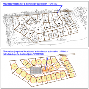
    Dear colleagues, sorry. I finally understood where the misunderstanding came from.  I had to make the right explanations for the pictures.

    There are no overhead lines and no single feeders on the plan above. There are no overhead lines in this project.

    The picture above shows the result of the MeteorSPEC's work - the cartogram of consumers (circle area is proportional to power demand) and the procedure of determination of theoretically optimal location of a substation.

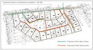
    Currently designed cable routes are located as follows:
    0f4abc065c1e559ed8725a6d23abbcf1-original-image.png


    OK - understood


    The architect location does seem to optimize the cable costs on the HV installation, and a bit of fiddling with the LV feeders wouldn't go amiss. It also seems to allow direct DNO access from the feeder road and clearly the aesthetic is considered as improved.


    Have you actually worked out the differences in LV cabling losses for both options and then included the reduction in HV costs. Just by observation, there would seem to be 4/5ths of the square root of not very much difference (particularly when you take on board the point about transformer losses dominating)


    Regards


    OMS


Reply
  • Former Community Member
    0 Former Community Member
    Alex Juhanson:
    Dear colleagues, sorry. I finally understood where the misunderstanding came from.  I had to make the right explanations for the pictures.

    There are no overhead lines and no single feeders on the plan above. There are no overhead lines in this project.

    The picture above shows the result of the MeteorSPEC's work - the cartogram of consumers (circle area is proportional to power demand) and the procedure of determination of theoretically optimal location of a substation.

    Currently designed cable routes are located as follows:
    0f4abc065c1e559ed8725a6d23abbcf1-original-image.png


    OK - understood


    The architect location does seem to optimize the cable costs on the HV installation, and a bit of fiddling with the LV feeders wouldn't go amiss. It also seems to allow direct DNO access from the feeder road and clearly the aesthetic is considered as improved.


    Have you actually worked out the differences in LV cabling losses for both options and then included the reduction in HV costs. Just by observation, there would seem to be 4/5ths of the square root of not very much difference (particularly when you take on board the point about transformer losses dominating)


    Regards


    OMS


Children
No Data