This discussion has been locked.
You can no longer post new replies to this discussion. If you have a question you can start a new discussion

Insulation Resistance Measurements

Former Community Member
Hello,


We have a Insulation Resistance measurement unit from Hioki - ST5520.

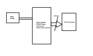
We are using this to measure multiple devices controlled through a relay matrix as shown in the figure. The positive and negative terminals of the ST5520 is multiplexed through the relay matrix to the 64 pins of the connector. There are 7 pcb's each containing 20 relays.

The individual board testing from ST5520 to the connector is giving a open condition result with a high value of insulation resistance of 9.90Gohm @1000V, when there is no load at the connector output, it is left open.

But the when the whole system is wired and tested with the 7 pcb's(all 32 channels), the value fluctuates and starts with a value from 100Mohm and eventually reaches open condition value.

Is there a problem with this process of multiple channel testing? or this is the expected behaviour? the open condition value(9.90Gohm@1000V) is maintained once it reaches this value and further tests result in this same value. 

Once the system is left OFF for a period of a day, then the testing is resumed again, the same behaviour of starting from 100Mohm to open condition value repeats. Is this to be expected or i am understanding/ doing something wrong?

Any help with this is much appreciated. Thanks in advance.
0d3eb1e11f9f4ba9176cae1b22dc1e68-huge-insulation-measurement.png
Parents
  • Putting the question in reverse, how much resistance can be added in shunt with the PCB being tested before it fails to perform the desired function ? - it may be worth trying to set the fail limit to 5 or ten times that, rather than looking for the highest the meter can detect,  assuming  the answer is not gigohms, in which case the finished product will need a lot of environmental protection.

    Be aware that the meter will internally be configured to cancel the effects it's own current drawn as best it can, and it does not mean the meter has internal resistance as high as it can measure - there are lots of tricks with instrument design that are used to get the optimum sensitivity.
Reply
  • Putting the question in reverse, how much resistance can be added in shunt with the PCB being tested before it fails to perform the desired function ? - it may be worth trying to set the fail limit to 5 or ten times that, rather than looking for the highest the meter can detect,  assuming  the answer is not gigohms, in which case the finished product will need a lot of environmental protection.

    Be aware that the meter will internally be configured to cancel the effects it's own current drawn as best it can, and it does not mean the meter has internal resistance as high as it can measure - there are lots of tricks with instrument design that are used to get the optimum sensitivity.
Children
No Data