This discussion is locked.
You cannot post a reply to this discussion. If you have a question start a new discussion

Insulation Resistance Measurements

Former Community Member
Hello,


We have a Insulation Resistance measurement unit from Hioki - ST5520.

We are using this to measure multiple devices controlled through a relay matrix as shown in the figure. The positive and negative terminals of the ST5520 is multiplexed through the relay matrix to the 64 pins of the connector. There are 7 pcb's each containing 20 relays.

The individual board testing from ST5520 to the connector is giving a open condition result with a high value of insulation resistance of 9.90Gohm @1000V, when there is no load at the connector output, it is left open.

But the when the whole system is wired and tested with the 7 pcb's(all 32 channels), the value fluctuates and starts with a value from 100Mohm and eventually reaches open condition value.

Is there a problem with this process of multiple channel testing? or this is the expected behaviour? the open condition value(9.90Gohm@1000V) is maintained once it reaches this value and further tests result in this same value. 

Once the system is left OFF for a period of a day, then the testing is resumed again, the same behaviour of starting from 100Mohm to open condition value repeats. Is this to be expected or i am understanding/ doing something wrong?

Any help with this is much appreciated. Thanks in advance.
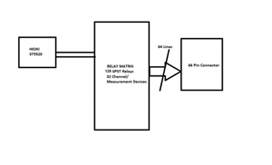
0d3eb1e11f9f4ba9176cae1b22dc1e68-huge-insulation-measurement.png
  • It looks like a question that is off my pay scale.


    But is the answer simply you are measuring multiple resistances in parallel and it takes time to "charge" the system? 


    1/Rt = 1/R1+ 1/R2+1/R3+1/R4+1/R5+1/R6+1/R7


    Andy Betteridge
  • starts with a value from 100Mohm and eventually reaches open condition value.

    :

    Once the system is left OFF for a period of a day, then the testing is resumed again, the same behaviour of starting from 100Mohm to open condition value repeats.

    sounds to me that either there's some damp in the system that's being dried out by the test voltage (probably unlikely) or that all the PCBs and relays are acting as a reasonably large capacitor that takes time a charge up from the limited IR meter test current (possibly more likely). If it were the latter problem I might expect the 'slow ramp up' problem to return immediately if the IR meter's +ve and -ve leads were reversed (all presuming it's a DC test current).


        - Andy.
  • Presumably you are doing a timed test, unlike installation electricians who press the button and hold it down for a random period.


    So surely if it is a timed test being carried out in accordance with the required standards, if it passes at the end of the timed period everything is hunky dory?

    https://www.hioki.com/en/products/detail/?product_key=5780


    Andy Betteridge


  • Former Community Member
    0 Former Community Member
    Thanks for the Reply.


    At any point of time only a single channel connection is propagated from ST5520 to connector, so dont think that we are measuring multiple resistances.

    The connection is not propagated to multiple channels. This is what you meant when talking about multiple parallel resistances right? even if the signal is propagated through multiple channels the end connections are open with no load, so i think it should still show open connection, am i wrong to assume that?

  • Former Community Member
    0 Former Community Member
    Thanks for the Reply.


    Initially we also assumed that former condition you mentioned and took steps to avoid that, but the result was still the same, so that is ruled out.

    will check and get back after testing the reversal of +ve and -ve leads.

    Lets assume that the large charge up is the problem, is there a way around it? Right now the time it takes for the ramp up is rather large.
  • Former Community Member
    0 Former Community Member
    Sparkingchip:

    Presumably you are doing a timed test, unlike installation electricians who press the button and hold it down for a random period.


    So surely if it is a timed test being carried out in accordance with the required standards, if it passes at the end of the timed period everything is hunky dory?

    https://www.hioki.com/en/products/detail/?product_key=5780


    Andy Betteridge


    Thanks for the reply. 


    Yes we are doing a timed test, which is though the software commands, not the buttons on the ST5520. 

    The problem with the result now is that it is taking lot of time to reach the open condition and the setup is open ended with no load. Ultimately this has to be tested with the load, we cannot wait everytime for the system to reach open condition and then connect the load.


  • The only question is "what is the pass IR value in the test spec?". As soon as this is read by the computer you go on to the next path. The actual value doesn't matter, only that the pass value is reached. This should enable you to flash through all the tests in a few minutes. The reason it takes time to get to the GOhm region is because of something called "dielectric absorption", but it is not really related to the IR measurement. Your insulation tester is providing a few microamps to do the test, and this is effectively the time constant of the capacitance you are seeing.


    Edit: Explaination added


    Regards

    David CEng etc.
  • Former Community Member
    0 Former Community Member
    davezawadi (David Stone):

    The only question is "what is the pass IR value in the test spec?". As soon as this is read by the computer you go on to the next path. The actual value doesn't matter, only that the pass value is reached. This should enable you to flash through all the tests in a few minutes. The reason it takes time to get to the GOhm region is because of something called "dielectric absorption", but it is not really related to the IR measurement. Your insulation tester is providing a few microamps to do the test, and this is effectively the time constant of the capacitance you are seeing.


    Edit: Explaination added


    Regards

    David CEng etc.


    Thanks for the reply.


    Yes, read about "dielectric absorption". So we waited to measure the time taken to reach a high value. But the issue is that the time it is taking to reach a high value is in the range of 10-20mins approx for each channel. This is producing a huge overhead. The loads to be measured has an optimum IR value in the range of several hundred Mohms to 2-3Gohm, so the pass value should be higher than this to accurately measure the readings. So due to the large time taken for the pass value , the "dielectric absorption" doesnt seem to answer the issue completely. or is my understanding incorrect and the time measured is the actual time taken and will always be present? If so is there a way to reduce it?


  • As David said, you need to check what insulation test result value is accepted as a pass, not assume that the meter can or will show an over limit reading and anything less is unacceptable.


    I bought a Megger MIT420/2 a Saturday night Ebay bargain, brand new from a motor factor who presumably had been convinced that car mechanics were going to buy them to test EVs, it does timed tests and has features I have never used, it measures to 200 giga ohms I would be waiting a hell of a long time for that meter to go over limit on the jobs I have, it sometimes gets to 2 or 3 giga ohms but that's it.
  • At 1000V you will be seeing all the effects insulation can throw at you in everything, the PCBs,  the relays, perhaps the flux used to solder the PCBs, and any finger prints on the exposed ends of wires -  everything will matter at this level of resistance - to get the best part of 10 gig-ohms, you are asking for  something like 100nA or less to flow, now that  that is a mere 10^12 electrons per second. - what area of insulation are you stressing -  each atom is ~ 250pico metres radius, or if you prefer to think of it as atoms, then each square mm of insulation to live metal interface exposes about  16 million million atoms, it is not reasonable over many hundreds of square mm of contact area between insulation and  live metal not to expect a detectable percentage of the atoms to have either a free electron (steady leakage current ) or a slightly wobbly one (slow polarisation and dielectric recovery)


    If you really do need to measure giga-ohms on the test specimens, then you need to be gapping the insulation to give longest possible creepage paths and large clearances to keep the E field down, cleaning everything till it gleams, baking it to drive of moisture and then encapsulating as much as possible in HV laquer, or alternatively after cleaning and bake off, doing the whole test in vacuum. 

    Can you test at lower voltage ? - if the resistance looks higher , you may also be suffering the onset of corona discharge to the air. This can be tracked down, either using a MW radio, or a UV detector. (or just hopefully polishing off all surfaces that are not smooth - cut wire ends make quite good needle electrodes.)


    But before all that, as others have said, check if you really do need to measure 10 gigohms, or if a lower pass limit can be set - a few million ohms is normally OK for a  a wiring installation, and much easier to handle.