This discussion is locked.
You cannot post a reply to this discussion. If you have a question start a new discussion

PAT Substitute Leakage Test

Hi.


Have a question on voltages and equipment regarding a PAT test option.

On some equipment, like motors, if the voltage drops below the minimum, damage can occur. In the case of motors, from overheating.

Not sure what the effect would be on electronics. I believe the inductive reactance may reduce like it would if the frequency went down. Not sure if it's the same case with voltage.

I was looking up PAT testers the other day. I did the C&G PAT course years ago and the last time I used PAT tester is about 15 years ago.

There is now an option to do a "Substitute leakage current test".

Depending on the tester it is between 60 & 100 volts.

I would have thought the only way to get leakage is for the equipment to be running and that would take full voltage.

I can't see how using a voltage so low will get a leakage result. I'm also wondering if there is any adverse effect on the equipment. I scanned through the Fluke manual and it didn't have any restrictions on the type of equipment.

I know they are unlikely to produce the tester with this test if it damaged equipment.

I'm theorising that even if equipment can get damaged if the voltage drops below the minimum, the test voltages that are much lower are not enough to run equipment so no damage can occur.

Still can't see how you can get a leakage result though.


Any thoughts?
  • I have a similar question.

    During a PAT test on a handheld Black & Decker jigsaw, the saw was being held by the tester so he could pull the trigger while his mate pressed the button on the test machine, The jigsaw ran for a while then the meter said it had failed on earth leakage,(1mA)  but this was a Class 2 device with a 2 core cable so where was the leakage going to?

    Surely we can't have a situation where the device would have passed if the tester was standing on a rubber mat or had trainers on and would fail if he wasn't / didn't?
  • This shows exactly what is wrong with PAT in general. A leakage test to real Earth is useless for a class 2 appliance, and should not be carried out. An insulation test to external metalwork probably should be. It is assumed by these supposed "testers" that all appliances are identical, and need the same tests. The persons carrying out the tests know no better, and so it goes on. I wonder what value they got for the Earth bonding to the appliance, was the infinity a pass? PAT should not be an idiots game, it requires competent inspectors in the same way as everything else. Why this reading was obtained needs investigation as there is no obvious circuit. I think at first guess that the tester is class 2 and has an Earth connection whose current is measured during the testing to get a "leakage" value. Stray capacitance from Live to Earth would then give some reading like this. The other alternative is that the saw insulation is faulty, but if this was not measured, who knows?
  • I guess it depends what "leakage current" test you are talking about.


    I agree that the usual "leakage current" test (residual current method) is less than satisfactory for general PAT test ... but if done under the proper conditions for the right reasons, I see no problem with it.

    Even with Class I equipment, I think the limits on some PAT Test instruments is very questionable, there are a lot of items of equipment now where the product standard might permit well above the 3.5 mA limit (on an appliance with a "standard" plug, i.e. BS 1363-1 in the UK).


    However, the touch current type "leakage current" test (if applied properly) is almost certainly an important test for electronic equipment ... more so since EN 62368 is taking over from EN 60950.
  • As far as I know the substitute / alternative leakage test is conducted in the same manner as an IR test with line and neutral shorted and tested to earth. The test voltage is around 100v but at 50Hz AC thus permitting impedance to be assessed. The machine then scales the leakage current to 230v. Problem is that electronic switches wont be activated so I guess this is not really a suitable in-service test for most equipment.
  • The problem, lyledunn, with this is that given a class 2 device there is no obvious earth to test it to. Do you use the plastic housing, the hand of the guy holding it or stick a probe into the ground somewhere?

  • The problem, lyledunn, with this is that given a class 2 device there is no obvious earth to test it to. Do you use the plastic housing, the hand of the guy holding it or stick a probe into the ground somewhere?

    I'd agree with the above comments that it's probably not a suitable test for a Class II appliance for an in-service test. Where insulation or similar tests are done on Class II appliances for things like type testing I understand that they'd wrap accessible bits of the appliance in foil which is then Earthed (at least in the sense of being connected to the "earth" terminal of the test meter) - and likely placed on an insulating surface, and if necessary any trigger being held in by mechanical means. Probably way beyond reasonable for a routine in-service test.


       - Andy.
  • Lyledunn

    Thanks. That makes sense for the substitute leakage test.


    From what I understand about how the normal leakage test is done it does not measure the current to earth but the imbalance between line and neutral in the same way as you can use a earth leakage clamp meter.

    Maybe the reading is a false one due to the commutator on the motor.


  • If you have a double insulated drilll with a metal chuck perhaps one can meaningfully measue an earth leakage of sorts, or at least verify the insulation is intact between the motor parts and the chuck.


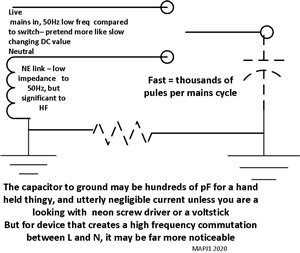
    The RCD like test (a current transformer looking at L-N currnets) is all very well, but can be fooled, in much the same way as an RCD is sometimes tripped by the failure of a light bulb filament. If the current waveform is jerky, that is to say it contains high frequency interruptions and reconnections, perhaps with peaks many times the average, then the action of the transformer can be/ to not correctly cancel the currents, and to register a peak reading on the secondary that is misleadingly high .f8c1f1f129aaf348ef7921c9ed72be71-original-emc1.jpg